Meanwhile, blade thickness was optimized to achieve the same level of reliability as with previous impellers.
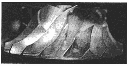
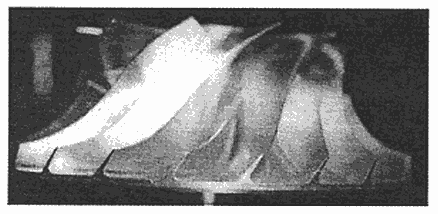
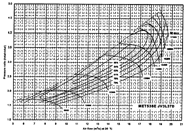
A photographic comparison of the GV3J and JV3L model impeller wheels is depicted in Fig.5, and the compressor map of the JV3L model is presented in Fig.6. Despite a 12% increase in capacity compared with the GV3J, sufficiently high compressor efficiency and pressure ratio are achieved.

JV3L impeller

GV3J impeller
Fig.5 Side views of compressor impeller wheels

Fig.6 Compressor performance map of JV3L impeller
3.2.2 Reliability
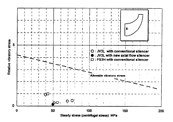
Given the high blade height of the new JV3L impeller wheel, care had to be taken in assuring the vibratory strength of the blades. Accordingly, vibratory stresses of the impeller wheels used in the MET53SE and MET90SE turbochargers were measured. The relative vibratory stress of a conventional impeller wheel and that of the JV3L are presented by means of the Goodmann diagram in Fig.7. Optimization of the blade thickness allowed vibratory stress to be held down to no more than that for the conventional model. Also, as noted below, the adoption of an axial flow type silencer for the MET90SE helped to reduce stress in comparison with the use of conventional silencers.

Fig.7 Goodmann diagram of JV3L impeller
3.3 Large capacity turbine
Turbine capacity is determined according to conversion area Ft, as obtained from turbine blade area Fm and nozzle area Fn in the following formula:

Expanded nozzle area Fn leads to greater turbine reaction, thus inducing a decline in efficiency in the high pressure ratio region. Also, the thrust force acting at the rotor increases due to the increased pressure differential at the turbine moving blade inlet, with the resulting problem of increased load on the thrust bearings.
BACK CONTENTS NEXT