Flow rate of the main air and of reheat hydrogen is measured by orifice flowmeter and by thermal mass flowmeter respectively. Combustion gas temperature is measured by R-thermocouples at the inlet of the reheat section and its outlet.
Combustion gases are sampled at four points assigned in the radial direction with an equal sectional area both at the inlet and the outlet of the reheat section. Mean values of 4 measured values at each section are regarded as data. Gas concentrations are measured by gas chromatograph for hydrogen, by paramagnetic oxygen analyzer for oxygen and by chemi-luminescenece NOx/NO meter for NOx. In order to avoid the effect of NO2 solution in condensed water, the sampling probes were cooled with water at around 333 K. The lines from sampling probes to the electronic cooling dehumidifier were heated at around 363 K by electricity and an NO2/NO converter was set before the dehumidifier.
Suppose the reheat gas turbine with a turbine expansion ratio 2, the temperature of the working gas gets down from about 1573 K (1300亷) to about 1373 K (1100亷). Therefore, in the present expreriments, the inlet temperature of the reheat section was set at about 1373 K and 1073 K for comparison, and the combustion loads in the reheat section were set equivalent to the gas temperature increases of 100 K and 200 K. At the main air flow rate of 6200 mol/min, the reheat loads are equivalent to 18 kW and 36 kW respectively.
In this paper, the combustion gas temperatures are expressed in the adiabatic flame temperatures calculated from the flow rate of air and fuel and the combustion efficiencies are based on the lower heating values of unburned hydrogen, methane and carbon monoxide.
丂
2.2 Combustion Characteristics of Reheat Process
The combustion efficiencies of hydrogen at the exit of the main combustor were more than 99.99%, since the concentrations of the residual hydrogen were less than 10 ppm at the combustor exit temperatures between 1090 K and 1430 K. Therefore, at the inlet of reheat section, combustion gas consists mostly of nitrogen, oxygen and vapor.
The combustion efficiencies in the reheat process are shown in Fig.8. The combustion efficiency is defined as (Qf-Qu)/Qf, where Qf is total heat release which would have been from supplied fuel and Qu is heat which would have been released from unburned element (hydrogen, methane and carbon monoxide). Heat releases from unburned elements are calculated as low heat value based on the gas analysis results.
丂
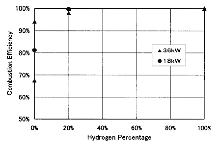
Fig.8 Combustion Efficiencies of Hydrogen, Methane and Mixture in Reheat Process
丂
In the case of the 100% hydrogen reheat fuel, the combustion efficiencies were almost 100% for the reheat loads of 18 kW and 36 kW when the inlet temperature of the reheat section was over 1090 K.
On the other hand, in the case of the fully methane reheat fuel (0% hydrogen), stable ignition could not be achieved at the inlet temperature of around 1090 K. For the stable ignition, the inlet temperature of the reheat section was increased to 1460 K. The data for the methane reheat shown in Fig.8 are under that condition. At the reheat load of 18 kW, the combustion efficiency was 81%, and at 36 kW, the combustion efficiency was between 68% and 94%. Despite a rise of inlet temperature, the combustion efficiency of pure methane reheat did not reach to 100%. With the aim of the improvement in the combustion efficiencies, hydrogen was added by 20%.
Fig.9 shows the NOx emission indices both of the main combustor and the reheat section in the case of the pure hydrogen at reheat load of 36 kW. Here the NOx emission index (EINOx) was defined as NOx production per unit heating value of the fuel. It means that 2300 times of EINOx value approximately correspond to the amount of NOx emission (g unit, converted value to NO2 ) per 1 kg of methane. The combustion efficiencies reached to 100% for 18 kW and 98% for 36 kW.
Although the both combustion at the main combustor and the reheat section is diffusive, the emission index of the reheat section was much smaller than that of the main combustor. EINOx at the reheat section was one eighth to one fourth of that at the main combustor. With the increase of the inlet temperature, the emission index became higher.
丂
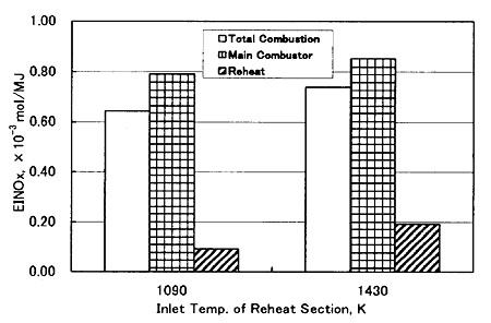
Fig.9 NOx Emission Indices of Hydrogen both in Main Combustor and Reheat Section (Reheat Load of Hydrogen = 36 kW)
丂
Fig.10 shows the EINOx in the case of reheat by pure methane for different two reheat load cases (Inlet temperature of the reheat section is about 1430 K). The EINOx for total combustion of both reheat load showed the almost same value (0.0007 mol/MJ); any influence of the difference of reheat load seemed not to exist. Similar to the pure hydrogen reheat shown in Fig.11, the emission indices of the reheat section were much smaller than that of the main combustor. But in this pure methane reheat case, it should be mentioned that combustion efficiency was lower as shown in Fig.8.
Fig.11 shows the EINOx in the case of reheat by methane with 20% hydrogen in mixture. Also in this case, any difference of EINOx caused by reheat load difference could not been observed, as same as in Fig.12. But, differing from the case of pure hydrogen and pure methane, the emission index of the reheat section was close to that of the main combustor.
In Fig.12, the influence of reheat to the ratio NO/NOx is shown for two cases of inlet temperature. Reheat load was 36 kW (by 100% hydrogen). NO/NOx is reduced by the reheat and this tendency is more obvious under the lower inlet temperature condition.
丂
丂
丂
BACK丂丂丂CONTENTS丂丂丂NEXT
丂