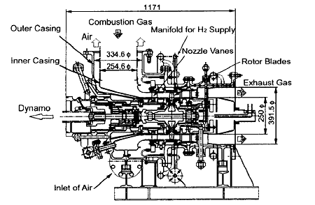
Fig.2 Cross Section View of Experimental Turbine
In this turbine, as indicated above, the hydrogen gas for the internal reheat is injected into the burned gas flow from the holes at the trailing edge of the nozzle vanes (Fig.3). It means that the space between the nozzle vanes and the rotor blades is regarded as that for combustion of the discharged hydrogen gases.
A series of experiments with it were carried out and the results showed the possibility of its realization [3] [4].
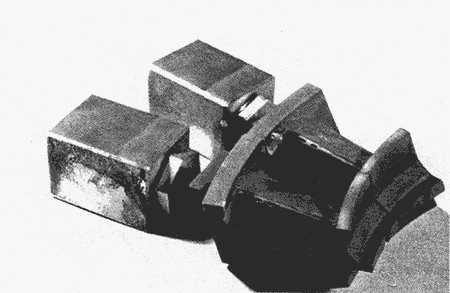
Fig.3 Nozzles Vanes
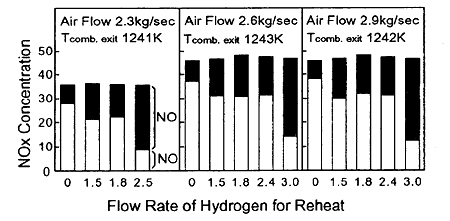
Fig.4 NOx Concentrations of Exhaust Gases
In the series of experiments, it was observed that the reheat process slightly increased the amount of NOx in exhaust gas, but the ratio of NO to NOx was diminished by the reheat process (Fig.4) and its tendency had a correlation with the concentrations of the unburned hydrogen gases in the exhaust gas.
In this study, in order to clarify the combustion characteristics of the reheat process at a higher temperature, at a higher reheat load and in a combustion gas stream fueled with hydrogen, an experiment of hydrogen bleeding from a rod in a high temperature wind tunnel was carried out. In addition to this, experiment of mixture of hydrogen and methane was carried out in view of expanding fuel usage.
2. COMBUSTION CHARACTERISTICS IN REHEAT PROCESS
2.1 Experimental Apparatus
In order to see combustion characteristics of the reheat process at a higher temperature, at a higher reheat load and in a combustion gas stream fueled with hydrogen, an experimental apparatus was set up as the outline shown in Fig.5. The main combustor (Fig.6) is of a single can type with reverse flow designed for a 200 kW emergency gas turbine fueled with kerosene[5]. Its fuel nozzle was replaced to the multi-hole type one for the usage of hydrogen as fuel. Main air is supplied in the atmospheric temperature and pressure.
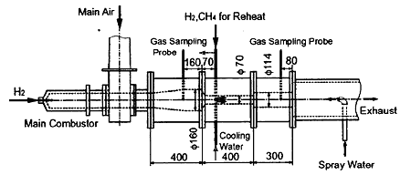
Fig.5 Experimental Apparatus for Combustion in Reheat Process
The reheat section is made of east cement with an inner diameter of 70 mm and length of 400 mm. Hydrogen for reheat is discharged downward from a water cooled stainless steel rod of 12 mm outer diameter and 6 mm inner diameter with three discharging holes (see Fig.7). The temperature of the reheat fuel is measured by the K-thermocouple inserted into the rod.
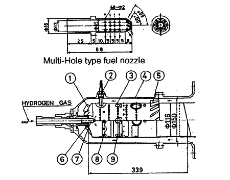
Fig.6 Main Combustor and Its Fuel Nozzle

Fig.7 Water Cooled Rod for Discharging Reheat Gas
BACK CONTENTS NEXT