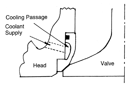
The frustration to ship owners was caused by the fact that the time to failure varied considerably so that some valves on an engine might last 1,000 hours and others 5,000 hours. Many efforts have been made [6] to fully understand the mechanism of the hot corrosive products largely resulting from vanadium and sodium in the fuel. Materials such as Nimonie 80A and 81 with their superior corrosion resistance gave some improvement, but the real breakthrough came when designers managed to reduce the temperature of the valve and seat to below the melting point of the corrosive products. Directly cooled valve seat inserts, as shown in figure 6, are now almost universally used, while improvements to turbochargers and combustion have kept the thermal load under control. An exhaust valve life of 10,000 to 15,000 hours can now be achieved.

Figure 6 - Direct cooled exhaust valve seat insert
2.4 lnjector nozzles
Initial needle wear and sticking were largely dealt with by using harder materials, slightly increased clearances and by improved fuel treatment. Cold sulphur corrosion, as with liners, has been overcome by maintaining an adequate temperature to prevent condensation. At the other extreme nozzles should not be too hot or the needle seat will soften. Also, engines can suffer from trumpet formation which is when carbon from combustion builds up on the outside of the nozzle into a hollow trumpet shape which distorts the fuel spray. These eventually break off but cause a smoke problem before they do. The solution has been lower nozzle temperatures and better fuel injection control. Not too hot and not too cold is therefore the answer and we design today for the injector tip temperature to be kept between 150 and 180℃, though higher temperatures are acceptable if a nitriding steel is used.
2.5 Turbochargers
Cold sulphur corrosion was again met and showed itself in the turbine casings. Again a solution was to maintain a high enough temperature, either by air instead of water cooling or by improved design. A more serious problem was deposits building up on the nozzle and the wheel of the turbine. This is still a major problem today despite the many proprietary fluids which are used for turbine washing or the use of particles such as crushed nut shells. Cleaning parts of the turbine is relatively easy but to provide an overall cleaning process without dismantling is more difficult. There is strong evidence that fuel additives provide an effective solution at a realistic cost [7].
3. THE DEMAND FOR LOWER FUEL CONSUMPTION
Despite the cost benefits of burning heavy fuel the two fuel crises concentrated the continuing demand for lower fuel consumption. This continues today even though the price of fuel in real terms is lower than it has been for very many years.
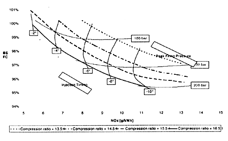
Perhaps the three most critical weapons the engine designer has used to attack the fuel consumption problem have been increased cylinder pressures, increased fuel line pressures and improved turbocharger efficiency. Figure 7 shows how fuel consumption is improved with increased firing pressure.

Figure 7 - Fuel consumption trade off
To take advantage of this significant benefit maximum cylinder pressures have been steadily raised. Marine engines today are designed to have a firing pressure above 180 bar in service with a potential for increases to over 200 bar. AVL and other companies have been exploring cylinder pressures of up to 250 bar. At this pressure further fuel consumption gains can be obtained, but there are problems of increased friction and piston ring life to be fully overcome so it may be some 10 years before such pressures are generally adopted.
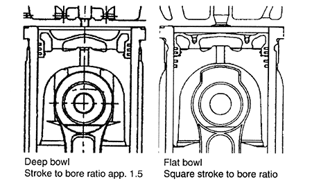
Figure 7 shows that to make best use of increased cylinder pressures, and incidentally to reduce NOx , it is necessary to raise the compression ratio. This would be a relatively easy thing to do were it not for the annoying habit of the intake and exhaust valves of both being open at top dead centre exhaust to provide scavenge air. To provide the required 2.5 mm clearance between piston and valve head it would be necessary to have deep cut-outs in the piston but these cause thermal stress problems and poor engine breathing. This dilemma has led us to increase the stroke of modem heavy fuel engines so that the distance between head and piston is greater and it is easier to fit in a combustion chamber which will give good performance. This is illustrated in Figure 8.

Figure 8 - Effect of stroke to bore ratio on piston design
BACK CONTENTS NEXT