Improved 4 1/2Carbon Seal
Operational experience with early service engines revealed improvement opportunities which could be made to the #4 1/2 carbon seal, located between the low rotor and high rotor shafts. As discussed earlier, this area benefited from the addition of the cold air buffer system which lowers seal operating temperatures. To further enhance the seal durability, the Phase II package incorporates an improved carbon seal material.
Improved Burner Temperature Profile
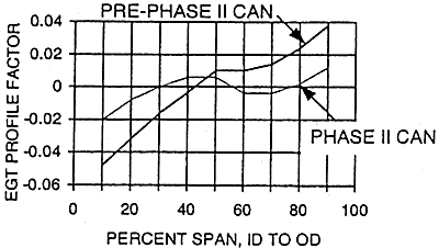
Analytical disassembles of high time service engines also revealed minor platform burning on the turbine first nozzle vane outside diameter platform which could result in rejection of first stage nozzle guide vanes during normal shop visits. To remedy this possibility, a burner can with a modified dilution hole pattern was developed to "flatten" the burner temperature profile thus reducing the outside diameter temperature. A comparison of pre-Phase II and the Phase II temperature profile is shown in Figure 10. As can be seen from this comparison the modified Phase II can lowers profile factor 2% at 90% radial span. This lowers hot spot temperatures 70。? at the burner exit plane, 35。? at the power turbine inlet plane. The development of the modified can initially began in a single segment burner rig. Once the can provided the desired profile in the rig, the profile was verified in engine testing.
RADIAL PROFILE AT EGT PLANE

Burner Can Improvement : Pre-Phase II vs. Phase II
FIGURE 10
Improved Design and Cooling of the Turbine Transition
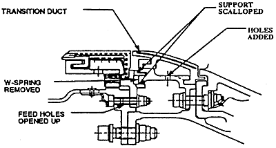
Operation and inspection of pre-Phase II service engines revealed distress in the gas generator turbine transition duct (see Figure 3 for location.) The distress seen was due to creep of the transition duct segments which over time resulted in segments impinging into the flowpath causing air blockage adversely effecting turbine operation. To eliminate the creep of the transition duct segment, 18% cooling air, added through the segment support to further cool the segment. The added cooling air results in a 50X creep life improvement and eliminates the possibility of transition duct distress. The transition duct assembly is shown below.

Phase II Improvement to Transition Duct
FIGURE 11
Phase II Validation Strategy
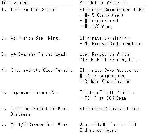
The total validation of the effectiveness of the Phase II program was a requirement prior to release to production and subsequent commercial use. P&W's validation strategy was based on defining very specific validation criteria for each aforementioned design improvements then use an engine test program to substantiate the validation criteria. If the criteria was not met, the improvement had to modified until total improvement validation has achieved. Table 1 is a list of the aforementioned improvements and the corresponding validation criteria :
TABLE 1

BACK CONTENTS NEXT