Control of the cold air buffer temperature is accomplished through an external heat exchanger and a variable speed fan controlled by a separate programmable logic controller (PLC). The speed of the fan is regulated to maintain 350°F (177℃) #4/5 supply temperature. The #6 supply temperature is maintained as a result of heat exchanger geometry. Air flow is regulated by 2 separate orifices in the #4/5 and #6 cooling air supply lines.
#5 Carbon Seal Piston Rings
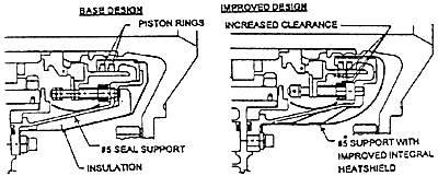
The #5 carbon seal piston rings provide radial sealing for the #4/5 bearing compartment. Like the #4/5 and #6 bearing compartments, operating time at high temperature caused these piston rings to varnish, inhibiting their radial movement. The result was poor sealing performance over extended operating time thereby allowing hot gases to leak into the secondary flows raising the engine scavenge temperatures above normal levels. The other phenomena which occurred was the occasional contamination of the piston ring grooves which also resulted in poor sealing performance. Debris from internal heat shields, for example, occasionally made its way into the piston ring grooves inhibiting the radial movement of the seal. This durability issue was resolved in the Phase II Package. The #5 piston rings directly benefit from the incorporation of the cold air buffer system reducing the seal housing temperature. In addition, an integral heat shield was also added to further reduce seal temperature. In terms of making the seal less susceptible to contamination, the piston ring groove width was increased to provide increased piston ring/groove clearance. Also, all non-encased insulation was removed to prevent the possibility of contamination. Figure 6 shows the pre-Phase II design compared to the Phase II design.

#5 Seal: Pre-Phase II versus Phase II
FIGURE 6
#4 Bearing Thrust Load
The #4 bearing is a duplex bearing which carries the thrust load of the high compressor rotor system. Figure 7 shows the dynamics of the high compressor thrust load.
TO BE ADDED LATER
FIGURE 7
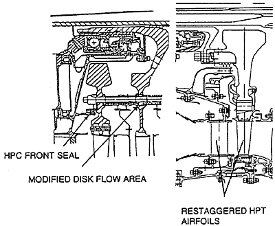
Early experience of the GG8 indicated that the thrust load to the #4 bearing could be reduced. To rectify the high thrust load to levels which yield full bearing life, the Phase II package made modifications to the front of the high compressor and changes to the high pressure turbine flow area. As shown in Figure 8, an air seal added to the front high compressor in conjunction with modifying the 8th stage disk flow area work to increase the pressure on the front of the 7th stage disk resulting in an increase rearward force, in the direction to unload the #4 bearing. Also, shown in Figure 8 are the modifications to the high turbine airfoils. These modifications include increasing first nozzle guide vane stagger and decreasing first rotor blade stagger. The result is increased pressure on the upstream side of the high turbine blades and a net force rearward, again in the direction to unload the #4 bearing. As will be discussed in the Phase II Validation section of this paper, load cell data from an instrumented engine confirmed the expected load reduction. The result is a #4 bearing which will yield full bearing life.

#4 Bearing Thrust Load Reduction Features
FIGURE 8
Intermediate Case "Funnels"
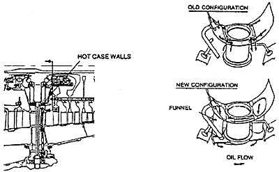
Analytical disassembly of a number of GG8s with high operating times reveal coke formation in the intermediate case which, if left to continue, could cause durability issues with the #2 bearing (rear low compressor bearing) and the #3 bearing (front high compressor bearing). As shown on Figure 9, this situation is prevented from occurring, by installing "funnels" to the intermediate case which reroutes hot scavenge oil away from the hot case walls thereby dramatically reducing the amount of coke production in the intermediate case. The funnels also serve to re-route any coke which may have been formed in the intermediate case to the scavenge oil filter system thereby isolating it from gas generator main shaft bearings.

GG8 Intermediate Case "Funnels"
FIGURE 9
BACK CONTENTS NEXT