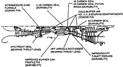
Each of the design features of the GG8 turbine were proven technologies from the PW2000 and PW4000 series of aircraft engines. Figure 2 is a cross section of the GG8 gas generator, PT8 power turbine and exhaust diffuser.

FIGURE 2
Initial Service Experience with the GG8 Gas Generator and the Development of the Phase II Program
Experience gained in 100,000 hours of initial commercial operation identified opportunities for GG8 reliability and durability improvements. The Phase II Program is a package of engineering solutions that addresses these improvement opportunities. By definition, the Phase II Program addresses all known causes of unscheduled gas generator removal. Therefore, the successful implementation of the Phase II Package would result in improved plant reliability and availability and a reduced unscheduled removal rates. The majority of the improvements concentrate on the mechanical components of the engine : bearing compartments, bearing thrust loads, and carbon seals. Figure 3 shows the major improvements that make up the Phase II Reliability Program. The following is a discussion and description of the improvements that are contained in the Phase II Program :

GG8 Phase II Improvement Package
FIGURE 3
Cold Buffer Air System
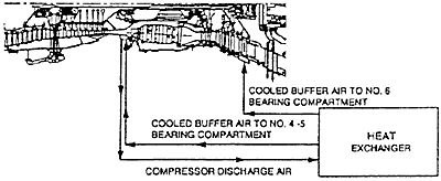
Early GG8 operation revealed a "time at temperature" phenomena which resulted in oil coke formation in the #4/5 (high spool) and #6 (low spool) bearing compartments. The obvious solution to this problem is to reduce the bearing compartments to temperature well below the oil coke threshold. This is accomplished very effectively with the incorporation of the engine cold buffer system which "bathes" bearing compartments with cooling air reducing compartment wall temperatures below oil coking levels. As shown in Figure 4,900°F (482℃) 13th stage compressor air is bled off the diffuser case is cooled through an external heat exchanger. It is then re-introduced to the #4/5 compartment at 350°F (177℃) via the diffuser case and the #6 compartment at 190°F (88℃) via the turbine exhaust case. This cooled air is then uniformly distributed throughout the compartment as secondary air flow within the engine.

Cold Air Buffer Scheme
FIGURE 4
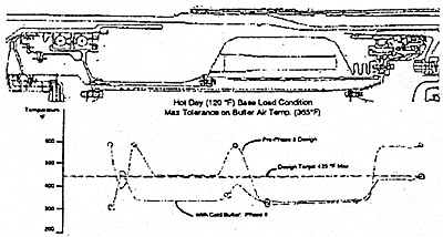
As can be seen in Figure 5, test data verifies the success of the cold buffer system in dramatically reducing the oil wetted surfaces in the #4/5 compartment. The oil coking temperature of generation 3 gas turbine oil is approximately 450°F (232℃). As shown, the pre-cold buffer system temperatures are above this level at certain compartment locations. With cold buffering, the temperatures are maintained below the 425°F (218℃) design target at base load even corrected to 120°F (49℃) ambient temperature, hot day operation.

Temperature Profile Across #4/5 Bearing Compartment
FIGURE 5
The cold buffer system has similar effects in the #6 compartment. Temperatures which were in excess of 400°F (204℃) are reduced to 250°F (121℃).
In addition to having a direct impact to the #4/5 and #6 compartments, other areas of the engine benefit indirectly with the addition of the cold buffer system. Temperatures in the #4.5 and #5 area also see reduced temperatures.
BACK CONTENTS NEXT