However, the advantage of the good conformability of narrow rings with the side of the groove becomes a disadvantage when heavy fuel is used, since it aggravates axial wear caused by the presence of abrasive wear debris. The greater susceptibility of extremely narrow rings to breakage has also contributed to their demise. Extremely wide rings should also be avoided because of the adverse inertia effect on the operating behaviour of the whole ring pack. It can be stated that the present ring width is a well balanced compromise from which optimum operating behaviour can be expected. The heat flow through the piston rings (a frequent topic of discussion) is in any case governed essentially by the design of the piston, especially in respect of cooling, and is no longer critical in the choice of axial width.
Axial wear, particularly in the presence of heavy fuel and combustion pressures above 180 bar, is countered by employing rings with chromium plated side faces (Fig 6) It is aproved that under the condition that hardened piston grove side faces are used not only the axial wear of the rings are reduced to the half but also the piston grove wear is reduced in the same Way. Normaly the wear of both partners is reduced to the half Today most of the heavy fuel engines are using side face chromium plated rings.
丂
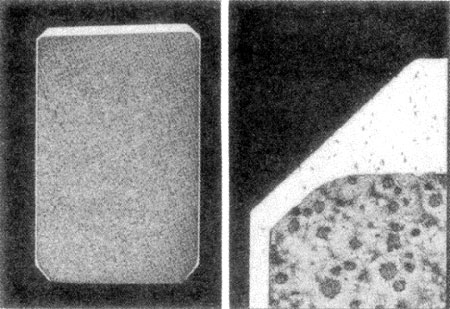
fig. 6 Piston Ring with Chromium Plated Side Faces
丂
1.4 Polar Shape
Application of the detailed polar shape required to produce a particular radial pressure distribution is currently achieved almost exclusively by cam turning, i. e. the ring is machined to its open, free shape by means of a mathematically defined cam. In the past the pressure distribution was established empirically, usually with a positive characteristic (Fig 7a).
丂
fig. 7 Characteristic Radial Pressure Distribution for Compression Rings
丂
Today rings for medium speed engines are given a round or negative characteristic (Fig 7c), and those for two-stroke engines a negative characteristic with total pressure relief at the gap (Fig 7d). The negative characteristic is intended to compensate not only for the progressively increasing gas pressure towards the gap, but in particular for the change in ring curvature as a consequence of thermal loading.
Nowadays, the free shape of the ring is calculated mathe-matically taking the known temperature gradient into account [1], and the same shape is utilized in specifying the copying cams for manufacture of the rings. This guarantees controlled deformation at operating temperature, thus ensuring optimum contact with the cylinder wall and the minimization both of ring wear and of the risk of scuffing and seizure near the gap especially during the running in period of high loaded engines. A further outcome is an increase in ring life.
Very important is also a correct assembling of the ring (Fig 8a). Many rings are destroyed by the use of wrong designed assembling tools. (Fig 8b).
丂
Fig. 8 Radial pressure distribution a) as produced b) after wrong assembling
丂
1.5 Fitted Gap
The high gas pressures in current engines call for careful tuning of the ring gaps to achieve optimum sealing; the top ring gap must be as small as possible but the second and third ring gaps should be significantly larger (Fig 9). By this means the top ring remains stable for a greater part of the operating cycle. In european engines the simple rectancular gap is today standard. It was shown that so called gas tight gaps or overlapped gaps are out of my view not necessary.
丂
Fig. 9 Compression ring Gaps for New Production Engines
丂
丂
丂
BACK丂丂丂CONTENTS丂丂丂NEXT
丂