The phase proportionality factor can be made dependent of the ignition delay and the fuel factor using a relation as

Also the shape constants for each of the phases can be made dependent of operating conditions. Correlations of both the phase proportionality factor and shape constants for a large number of engines are found in [17]. Successful use of this option normally requires adjustments of the model parameters according to experimentally obtained heat release diagrams.
In order to describe the low rate heat release at the end of the combustion, we have added an option to add a third phase described by a third Wiebe-function. This function is described by a second phase proportionality factor β2 , a relative starting point compared to the main combustion phase Δtcomb, a duration parameter Δtlate and a shape constant mlate. These parameters must be supplied by the user based on results from experimentally obtained heat release diagrams.
Valve model
The flow of gas through the intake and exhaust valves can be modeled using a one-dimensional quasi-steady compressible flow assumption. Assuming that the pressures, temperatures and gas compositions on both sides of the valve are known, the mass and energy flow through the valve can be calculated by the isentropic nozzle equation, expressed in compact form as :

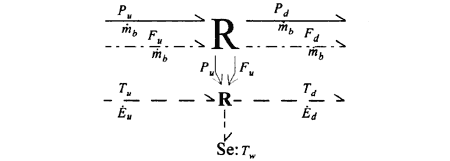
where A is the instantaneous valve flow area which is dependent on valve lift, C is the discharge coefficient which may be given as a function of valve lift and pressure ratio, and Pu, Pd, Fu, Tu, hu are the pressure, fuel factor, temperature and enthalpy on the upstream ( u ) and downstream ( d ) side of the valve respectively. The valve lift is calculated as a function of crank angle.
The valve model can be represented by an extended pseudo bond graph R-field implementing Eq. 4 as:
For the case of multiple valves the mass and energy flow is multiplied by the number of valves times a correction factor.

Fig. 5. Valve model - Extended Pseudo Bond Graph representation
The required input data for the valve model are a table of camlift versus crank angle, transformation ratio for the lever arm mechanism, the lever arm slack and valve reference area. All given for both air and exhaust valves respectively.
4.3 Air receiver / Exhaust receiver
The air receiver on a large marine diesel engine can often be modeled by a single volume with uniform pressure and temperature. The bond graph of the air receiver is given in Fig. 3.
Required input data for the air receiver or any general volume of uniform pressure, mixture and temperature are the total volume, and optionally a heat transfer coefficient and a single wall temperature.
4.4 Air cooler
The air cooler or intercooler, which is situated between the compressor and the air receiver and serves to increase the density of the air by lowering the temperature. Several models of this type of heat exchanger is available but here we select to describe a fairly gross version, where very little input data are necessary.
The air cooler is modeled as a heat exchanger where the change in air temperature is determined from the heat exchanger effectiveness, ε given as

where Tu,a, Td,a and Tu,w are the air temperatures upstream and downstream, and the water temperature upstream of the air cooler respectively. The heat exchanger effectiveness is either known as a design parameter or from correlation functions available from the manufacturers.
Assuming that the pressure drop across the heat exchanger can be modeled as a hydraulic restriction, the pseudo bond graph model for the heat exchanger can be given as shown in Fig. 6.

Fig. 6 Bond graph model of the air-cooler
The constitutive laws for the bond graph model of the air-cooler is given in Eq. (13).
BACK CONTENTS NEXT