3.2.3 SIMULATION REVERSE CONTROL
Past simulation and retraining can be easily realized by the time management function of the simulator.
Simulation reverse control function consists of the following functions.
(1) Backtrack
The instructor can return to the past training session (simulation) up to 2 hours long that is divided into every 5 minutes and restart the training session (simulation).
(2) Replay
The instructor can replay the past training session (simulation) up to 2 hours long that is divided into 5 seconds.
丂
3.2.4 MALFUNCTION CONTROL
By creating machinery malfunctions, various abnormal situations can be simulated as if onboard. The trainee can then experience plant operation under abnormal conditions.
The instructor can introduce failures and irregularities into the simulation model via the malfunction control function and, then visually and by instruments observe how the operator responds and takes action to bring the plant back to the normal condition.
The malfunction control function consists of the following:
(1) Malfunction set
The instructor can select and set the malfunction from among the malfunction list during training sessions (simulation). The instructor effectively can set the malfunction considering the plant status and timing of the training sessions (simulation).
(2) Malfunction reset
The instructor can reset the malfunction as necessary.
丂
3.2.5 EVENT LOGGING
By using the event logging function, the simulator can record training operations by all trainees. The simulations can then be reviewed later.
The instructor can watch the plant operation by trainees during the training sessions (simulation) and print out the operation event logging data sequentially via the event logging function.
The event logging function consists of the following:
(1) Logging the event data
(2) Displaying the event data
(3) Printing out the event data
丂
3.2.6 WHEELHOUSE CONTROL
The instructor can operate the ship in cooperation with trainees via the instructor workstation CRT display and mouse. The wheelhouse control function provides necessary information for the effective control of the speed of the main engine with normal operation via the instructor workstation CRT.
Wheelhouse control function consists of the following:
(1) Telegraph handle operation
(2) Steering gear operation
(3) Necessary indications for the main engine control
The wheelhouse control panel can be equipped separately.
丂
3.3 OPERATOR STATION FUNCTION
The operator station function has plant operation and monitoring software (function) in the simulated engine control room or simulated engine room with effective graphical user interface. The conventional mimic panel or graphic panel can be provided additionally as the customer's request.
丂
3.3.1 ENGINE MONlTOR
The engine monitor system function is provided for catalyzed observation to meet "unattended machinery space" operation. The displays, necessary indications and alarms are provided on the CRT display unit and are grouped functionally. The engine monitor system function faithfully realizes the actual engine monitor system onboard as a supplier of control and monitoring system for ship automation. The engine monitor system has each individual piping system status indication and is accurately simulated onboard system.
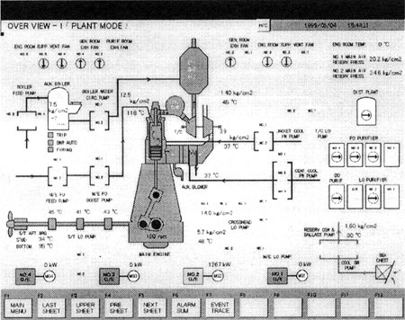
Furthermore, the simulator gives an overall indication of the system as shown in Fig. 6, so students can easily operate and understand the operating condition of the plant and machinery. The trainee can operate and monitor the major machinery of the engine plant by observing only the overview indication display function.
丂
Fig. 6 Display Example of Engine Monitor