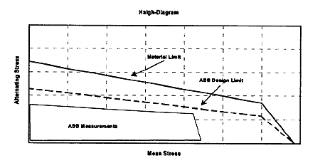
Fig.5: Amplitudes of resonances
2.1.2 Compressor
Two completely new compressor stages have been developed for the TPL turbocharger. These new compressors were designed using highly advanced, 3D computational methods for the fluid dynamics calculations. In spite of the flow simulations and non-linear finite element calculations of stress levels and blade vibrations, further optimisation of the design was carried out on the compressor and turbocharger test rig.
On 2-stroke engines the air amount raises significantly with increasing turbocharger efficiency. To make full use of the thermodynamic improvements on the turbine side, the diameter of one compressor was increased for the TPL..-B leading to a larger specific volume flow of 10% for the so called B11-version and almost 20% for the B12-version (Fig.6).
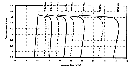
Fig.6: TPL..-B: Volume flow with the different frame sizes
In parallel with this the diffuser was further optimised and the efficiency rose by more than one point to a level of 87%, a remarkable figure for a radial single-stage compressor with a compression ratio of 4.2. The compressor efficiency for a TPL85-B12 is given as an example in Fig.7.
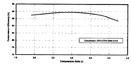
Fig.7: Compressor efficiency measured with a TPL85-B12
2.1.3 Bearings
The entire bearing assembly used in the TPL..-B turbocharger is identical to that used in the TPL..-A. Plain bearings were chosen as they ensure a long lifetime and stable operation, as demonstrated by the TPL..-A. The complete bearing assembly is shown in Fig.8.
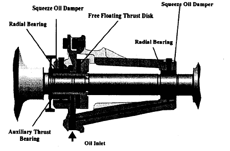
Fig.8: Bearing assembly of the TPL..-B
The non-rotating, radial bearing bushes are not fixed in the casing, but float in an oil-filled radial gap, which acts as a squeeze oil damper. This damper increases the stability of the rotor while reducing the dynamic forces, and hence the load on the radial bearings. Measurements of the shaft motion, with increased unbalance shown in Fig.9, verify the wide margin for direct contact of the shaft with the bearing bush resulting in a safe operation and a low wear rate.
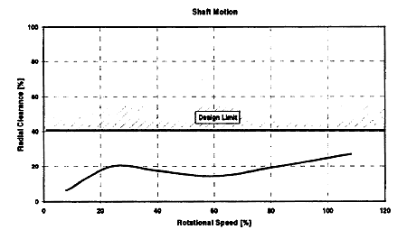
Fig.9: Amplitude of shaft motion
The main thrust bearing consists of a free floating disk between the rotating shaft and the stationary casing. This device halves the speed gradient in the axial gap, so that the losses and the risk of wear are significantly reduced.
The bearings are designed for 50μm mesh size filtration and direct lubrication by the engine lubrication oil system with an expected lifetime of 35,000 operating hours. First inspection results of TPL..-A turbochargers on HFO operated 4-stroke engines with 50μm filtration showed the bearings in very good conditions after more than 12,000 hours in operation (Fig.10). The oil temperatures used on 2-stroke applications are in general lower, leading to a larger oil film thickness in the turbocharger bearings. Therefore, considering the same oil filtration, even better conditions are expected for the TPL..-B bearings.
BACK CONTENTS NEXT