丂
3.1 Troubles related to the GI-technology
丂
When applying the GI-technology to the Chiba GIDE, the safety aspects were discussed in detail among the designer, the maker and the Classification Societies. The references 1), 2) include a discussion of these safety aspects, both for the external systems and for the internal systems.
In connection with commissioning of the engine in 1994, a Type Approval Test was carried out and the safety and control systems for the GI-technology were type approved by the five participating major classification societies.
Owing to additional safety devices and systems to prevent such situations as which might otherwise lead to failures, no major failure has been experienced until now and on this background the authors are convinced that the operation will continue without any safety hazard.
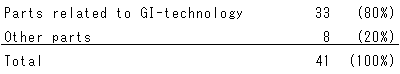
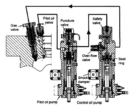
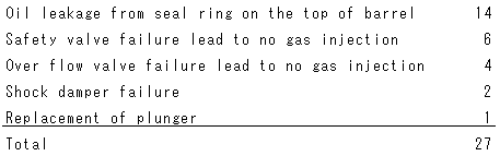
However, as mentioned above, the control oil pumps have given some troubles. The control oil pumps (shown in Fig.3) activate the gas injection valves. The design of the control oil pump is the same as that of the normal fuel pump, with two minor exceptions: an additional safety valve on the top, and an over-flow valve on the side. The latter works as high-pressure relief valve when the gas injection valve spindle is fully lifted (open). The total number of troubles related to the control oil pump was 27. Detail of these cases are shown below:
丂
丂
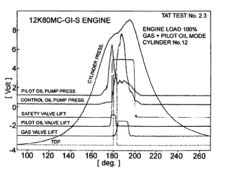
The control oil pump pressure is much higher than the pilot oil pump pressure as shown in Fig.4 at full load, so mechanical failure due to the high pressure was experienced while there were no troubles with the pilot oil pump at all. Oil leakage from the sealing ring on the top of the barrel was simply cured by changing the design as shown in Fig.5, and this was introduced as the standard for all MC engines. Mechanical failures of the over-flow valve spindle and the safety valve spindle have happened sporadically. A small design modification to avoid stress concentration and higher quality control of concerned parts will solve the problem completely.
丂