5. SIMULATION ANALYSIS AND EVALUATIONS
Figure 9 shows a timing pulse sequence of asymmetrical PWM gate voltage pulse signal to be supplied to each IGBT. In this figure, Duty Factor or Duty Cycle D serves as a control variable for the continuous power regulation for this CFVP quasi resonant soft switching inverter.
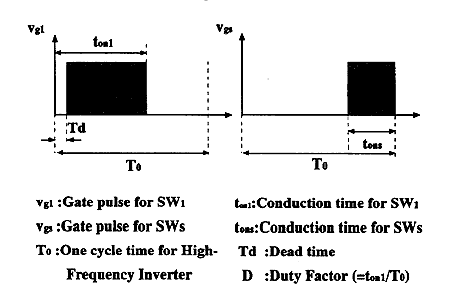
Fig.9 Asymmetrical gate pulse signals of Q1 and Qs
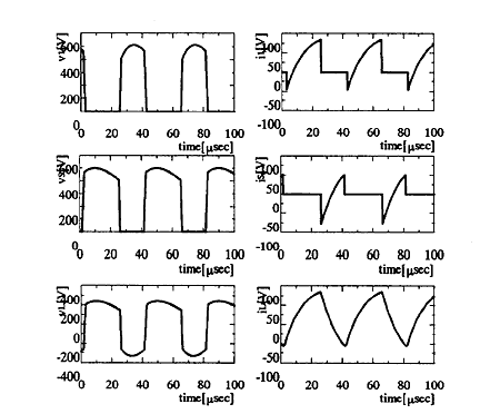
Fig.10 Steady-state voltage and current operating waveforms under a condition of D=0.6
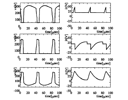
Fig.11 Steady state voltage and current operating waveforms under a condition of D=0.2
Figure 10 and Figure 11 show the steady-state voltage and current operating waveforms of the new quasi resonant inverter operating under a constant frequency variable power control strategy, which are illustrated by the computer simulation analysis in case of Duty Factor D=0. 6 and D=0.2.
When a Duty Factor D is below about 0.2, because of residual charges of the quasi-resonant capacitor C1 hard-switching mode (from mode 4 to mode 1) causes. In practice, this complete ZVS range can be used as so to achive a soft-switching operating range under an approximate ZVS condition.
Table 1 indicates the practical design specifications and circuit parameters of the feasible electromagnetic induction-based fluid-heating appliance using a quasi-resonant ZVS-PWM high-frequency inverter using IGBT modules.
Figure 12 represents input power vs. Duty Factor characteristics under a fixed frequency PWM control strategy. As can be seen in this figure, it is clearly proven that a Duty Factor D can be continuously adjusted in accordance with inverter output power adjustment under a principle of zero voltage soft-switching commutation.
Table. 1 Design specifications of experimental setup
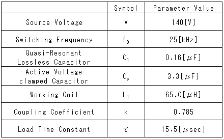
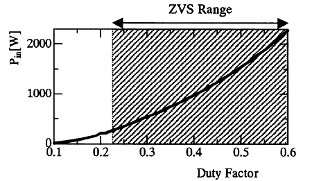
Fig. 12 Power regulation control characteristics
6. EXPERIMENTAL RESULTS AND DISCUSSIONS
Figure 13 shows a schematic novel prototype of electromagnetic induction eddy current based fluid heating appliance. The first stage saturated vapor generator can be and the second stage fluid heater can produce super heated steam over temperature ranging from 100℃-500℃; in some cases ranging from 200℃ to 1200℃..
Fluid temperature is detected at three points in appliance shown in Figure 13 and is able to be regulated by a PI controller. In experiment, the first and second stage electromagnetic induction fluid heaters are introduced by using high frequency soft switching inverter.
Figure 14, Figure 15 and Figure 16 depict the measured voltage and current waveforms of the main switching block; Q1 (SW1 and D1), voltage and current waveforms of auxiliary switching block; Qs (SWs and Ds) and electromagnetic induction based fluid heating load under a condition of Duty Factor D=0.6.
BACK CONTENTS NEXT