It is noted that a new conceptual induction-heated fluid heating appliance using voltage-clamped quasi-resonant ZVS-PWM high-frequency soft switching inverter using trench gate IGBT is able to be more cost effective.
4. QUASI-RESONANT ZVS-PWM HIGH-FREQUENCY INVERTER
4.1 Circuit Description
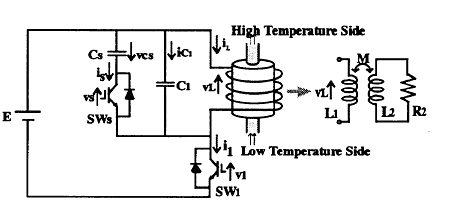
Figure 5 shows a high frequency load resonant inverter circuit topology for the electromagnetic induction-based fluid-heating appliance, which operates under a condition of zero voltage soft switching (ZVS), constant frequency, asymmetrical PWM control strategy over wide load range and duty cycle control ranges. This power electronic appliance using two cascaded high frequency inverters can solve a problem of harmful acoustic generating noise problem in multi inverter-fed induction heating fluid heating because of operating frequency modulated power regulation.
This high-frequency inverter is composed of a voltage-source type ZVS-PWM quasi-resonant inverter with a single active voltage clamped capacitor.
In general, this high-frequency quasi-resonant inverter with CFVP function is connected to a single-phase utility AC grid, full-bridge diode rectifier, non smoothing filter for a power factor correction function.
It is noted that a newly developed ZVS-PWM quasi-resonant inverter with a CFVP function is directly combined to each induction heating load vessel coupled to individual working heating coil.
Its control circuit for constant frequency power regulation and system protection schemes, and IGBT driver IC module circuit are incorporated into this high-frequency inverter fed fluid heating appliance which operates under a principle of ZVS. In this inverter circuit depicted in Figure 5, the reverse conducting power semiconductor switching block devices, auxiliary active switch; Qs (SWs and Ds), and main switch; Q1 (SW1 and D1) incorporate a new generation high-frequency and lowered saturation voltage type trench gate IGBTs designed for soft-switching.

Fig.5 Active voltage clamped ZVS-PWM high-frequency inverter
4.2 Circuit Operation
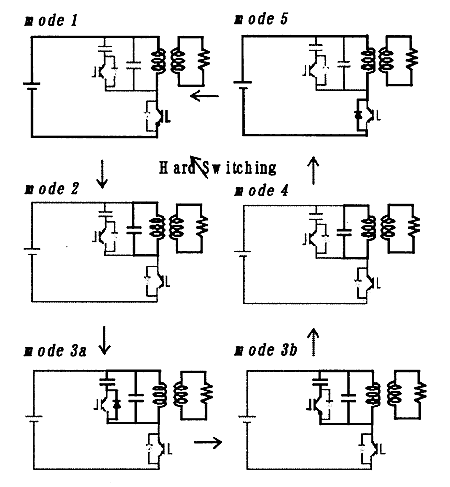
Figure 6 shows the equivalent circuit and steady-state equivalent circuit for each operation mode of this quasi resonant inverter. This inverter circuit operation for each mode is described as follows;
<Mode 1> When SWI is on, the source supply voltage E is applied on induction heated load represented by the R-L equivalent circuit model.
<Mode 2> At ton, SW1 is turned off. Current iL flows through C1. Its energy is delivered to C1.
<Mode 3a> When the voltage across C1 is equal to E-vcs-vC1, Ds turns on. Current iL flows through Ds.
<Mode 3b> When a direction of iL is reverse, iL also begins flowing to SWs. At T0, SWs is off.
<Mode 4> Current iL flows to Cs, the voltage vcs increases. When the voltage across C1 is equal to E, D1 is on. Current isw1 flows through D1.
<Mode 5> When current iL is equal to zero, DL is off. When current iL is equal to zero, mode 5 moves to mode 1.
The operation in steady-state is repeated cyclically.

Fig.6 Equivalent circuit for mode transition
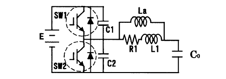
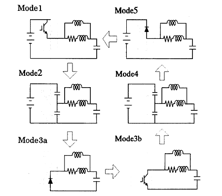
And, Half Bridge type high frequency inverter shown in Figure 6 is also examined and Figure 7 is mode transition of Half Bridge type high frequency inverter. The characteristic evaluation in high frequency inverter between figure 5 and figure 6 will be carried out in future.

Figure 7 . Auxiliary inductor-assisted half bridge high frequency inverter

Fig.8 Equivalent -circuits for mode transitions
BACK CONTENTS NEXT