3.3. TEST RESULTS
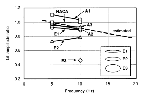
As an example of the test results, the first component of lift amplitude is shown in Figure 5., compared with that for the conventional blade section type (NACA00125). The lift amplitude ratio in the figure is the value of each lift amplitude devided by the lift amplitude for NACA00125. From the figure it is known that compared with the conventional blade section, lift amplitude was reduced for every six kind of the balde section except for one kind of A1 blade section with its trailing edge perpendicularly cut. With E2 and E3 of larger thickness/width ratios, the lift amplitude reduction is further remarkable. Besides, it is indicated that when vibration frequency became higher, the lift amplitude ratio was reduced; it could also be conjectured that supposing a high speed propeller for around 1200 rpm, with the trailing edge made insensitive or thicker, the lift amplitude ratio will be reduced by about 20% compared with a conventional blade section.

Fig.5 Comparison of special two-dimensional blade section and conventional blade section lift amplitude ratio
4. APPLICATION TEST USING MODEL PROPELLER
The test was to study the effectiveness of the propeller with a special blade section applied to propeller by contrasting the new propeller designed based on the results of such a test concerning dynamic characteristics of the special two-dimensional blade section to a conventional propeller.
4.1 MODEL PROPELLERS USED FOR THE TEST
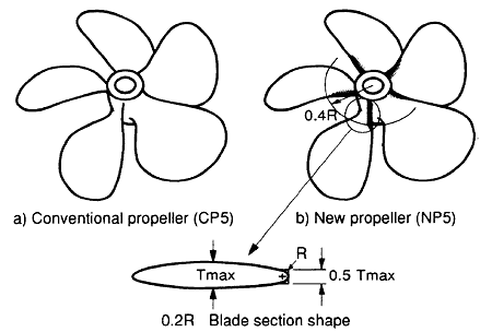
The model propellers used for the test were of two kinds of 3 blades and 5 blades, with each one model selected from the propeller particulars which had ever been applied to an actual application, and besides having been subjected to root erosion. The new propellers were based on the conventional propellers, however, with blade root part only revised to the new blade section's. The new blade section, whose root part only applied to the new propellers, had been designed so that the ratio of the trailing edge thickness against the maximum blade thickness should be 0.5, by referring to the elliptical blade section Model E 1 which showed low value in either of the effect of angle of attack variation on lift variation and of the lift amplitude at the tests concerning characteristics of the special two-dimensional blade section, where the trailing edge thickness gradually decreased radially, and smoothly connected at the radial position of 0.4 R to the blade secion of the conventional blade section. Table 2. shows the model propeller's principal particulars, and Figure 6. shows the 5 blade propeller appearance.
Table 2 Model propeller's principal particulars


Fig.6 Model propellers (5 bladed)
4.2 TEST METHOD
Propeller open test and cavitation were conducted for the four kinds of model propellers. The cavitation test was under the common propeller operating conditions with the shaft inclination by 10 deg. in accordance to the top ship speed operation. The Reynolds number, on the other hand, was 5 × 10⁵ in conformity with that for around the blade root of the two-dimensional blade section.
The test was conducted at The Shipbuilding Research Centre of Japan, an incorporated foundation, with the propeller open water test in the towing tank, the cavitation observation in the cavitation tunnel including photographing and sketching, and also the measurement of inwater noise.
4.3 TEST RESULTS
Figure 7. shows the cavitation generation condition at blade positions of 102° and 132° with the new 5 bladed propeller (NP5) and the conventional 5 bladed propeller being in comparison, as an example from the cavitation test results.
BACK CONTENTS NEXT