|
A SIMULATION ENVIRONMENT FOR PROTOTYPING, SIMULATION
AND TRAINING OF MARINE CONTROL SYSTEMS
Svein Peder Berge (MARINTEK, P.O. Box 4125 Valentinlyst, N-7450 Trondheim, Norway)
Gunnar Nyland (Rolls-Royce Marine AS, N-6065 Ulsteinvik, Norway)
Abstract: The Norwegian Marine Technology Research Institute (MARINTEK) has developed a Simulation Environment used for design, control prototyping, simulation and training of marine systems based on an industrial simulation standard; High Level Architecture (HLA). The simulation environment consists of hydrodynamic, control and visualisation modules (federates) running on several computers using an Ethernet network. The hydrodynamic modules of ship and propulsion are based on model tests, full scale tests and hydrodynamic experience at MARINTEK. Currently, we have a 6 degrees-of-freedom model of ship motion in waves. The control systems (autopilots, tracking system and joystick system) are all developed using the Mathworks products (MATLAB, Simulink, Real Time Workshop and Embedded Coder) to generate C-code. The same controller software can be used in the model ship, in the simulator and in the full scale application. An example presented in this paper is a simulator used to develop a joystick control system for a double-ended passenger catamaran ferry. The simulator is used in all development stages from initial idea until final industrial product using both software- and hardware-in-the-loop testing.
1. TECHNOLOGY
1.1 High Level Architecture (HLA) and Run Time Infrastructure (RTI)
The simulator consists of several modules as shown in Fig. 1. All modules of the simulator are connected using the Run Time Infrastructure (RTI) software and are exchanging data through this structure during a simulation. The exchange of data is described using the High Level Architecture (HLA) standard for simulation system. This HLA standard was originally defined by the Defense Modeling and Simulation Office of the United States Defense Department, and has now become an industrial standard (IEEE Standard 1516) [1]. The HLA is a set of definitions and rules that must followed to achieve proper interaction between the different dynamic modules in a simulation set-up. The RTI is the software that interconnects the modules.
Currently we are using the pRTI 1516 software from the Pitch company from Sweden. Basing the simulation process on the HLA/RTI ensures a standard, flexible and easy to use basis for different simulation set-ups containing different modules for different needs.
Fig. 1. Simulator Architecture based on HLA.
Simulator Architecture
2.2 Rapid Control Prototyping
To reduce the development time from idea to a final control system product, the Rapid Control Prototyping methodology is used. Rapid Control Prototyping is now widely used in automotive industry and become more and more used also for more complex control system designs, see [2]. The control software is developed in a graphical user interface, for example MATLAB/Simulink. The control software is based on standard components like integrators, digital filters, saturation blocks and in addition the user can program more user defined complex functions in S-functions. The graphical code is then compiled to standard ANSI C-code using the Real Time Workshop and Embedded Code toolboxes from The MathWorks Inc. The resulting C-code can be either used in the simulator or in the target system. The physical process that is to be controlled is first model using a mathematical model and the control software is tested in the simulator. This process is denoted as software-in-the-loop testing. All modules like the human machine interface (HMI) are developed using COTS components. After this stage, the real hardware is connected to the simulator. This is called hardware-in-the-loop testing. All modules are now replaced as far as possible with the final components and tested and tuned against the mathematical model of the process.
Finally, the hardware is installed in the real environment and the control software will run on a dedicated real-time platform.
Using Rapid Control Prototyping in control system design reduced the time to market. In NATO, a reduction of 30-50 % of time and cost has been documented using Simulation Based Design and Virtual Prototyping (SBDVP) [3]. Due to the fact that visualization software like terrain visualization and electronic chart system for ship navigation is now available for a low cost, the cost of developing a ship simulator as a part of a product development will be small compared to the extra costs for installation, testing and tuning time in full scale.
2. VISUALIZATION
2.1 Terrain and Ship Visualization
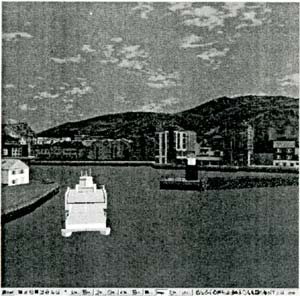
Fig. 2. Terrain visualisation in VEGA Prime.
To visualize the motion of marine vehicles in the surroundings, the VEGA Prime Software from MultiGen-Paradigm Inc. is used [4]. A typical visualization of ship and harbour is presented in Fig. 2. The terrain and 3D models are all based on the OpenFlight standard. Effects of shading, clouds, darkness and fog can easily be added to get a realistic impression. MARINTEK has developed a wave model, which will be included to get the correct response of the ship in 6 DOFs. The ship motion will then be correlated to real wave patterns.
2.2 Human Machine Interface
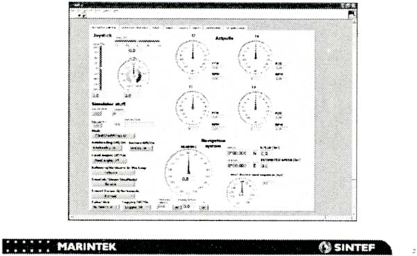
MARINTEK is currently using the LabView software from National Instruments Inc. to develop a human machine interface in an early design stage of the product development, see [5]. All virtual instruments and indicators like the heading, GPS and speedlog are presented on a standard portable PC. The interface to the simulator is based on a socket interface between Java and the LabView. Example of a typical user interface is shown in Fig. 3.
Fig. 3. Human Machine Interface implemented in LabView.
Human Machine Interface
2.3 Electronic Chart
In our simulations we are using the Olex chart system for visualization and navigation. This is a COTS product mainly used by fishing vessels [6]. Based on a GPS and echosounder the seabed or depth is automatically generated when using the system onboard. The depth information is then transferred back to the ship model to include the effect of shallow water. This Linux-application runs on a separate portable computer. Since the HLA provides communication across different software platforms, the Olex application is interfaced by simulating a GPS interface (NMEA 0183 protocol). A 3D view of ship and depth is shown in Fig. 4.
Fig. 4. Electronic Chart system - Olex.
|