|
Energy loss in the runup waves
By advantage of the concept of control volume to analysis the wave runup phenomenon.
In general, the wave energy will changed after the wave runup on a sloping dike (Fig.3) and the correlation
formula of the wave runup can to formulate as follows ( Cross and Solitt, 1972)
| where |
Ei |
 incident wave
energy (=1/2ρgAi2) incident wave
energy (=1/2ρgAi2) |
| |
Er |
 reflected
wave energy (=1/2ρgAr2, =1/2ρgAi2Kr2) reflected
wave energy (=1/2ρgAr2, =1/2ρgAi2Kr2) |
| |
E0 |
 wave energy
of overtopping wave energy
of overtopping |
| |
PE |
 potential
energy of the runup wave potential
energy of the runup wave |
| |
Kl |
 energy loss
coefficient energy loss
coefficient |
| |
Cg |
 group wave
velocity group wave
velocity |
| |
T |
 wave period wave period |
If the waves only runup and without overtopping, the above equation can to simplified as
Let pe = PE /ρgA2LR and substitute it into the above equation then
where k was the wave number.
Besides, from Figure 2, we can understand that
the dimensionless runup wave energy ( pe) can to calculated by the following equation
After integration, we have
| (Enlarge: 7KB) |
 |
At last, use this equation and equation (20) then the value of the relative wave runup height can be predicted.
Wave transmission and interaction
Seabrook and Hall (1998) proposed a calculation
formula for compute the wave transmission coefficient over a submerged breakwater as shown in equation
(1). If the submerged breakwater was impermeable and the surface of the submerged breakwater was smooth
(that means frictionless) then equation (1) can to simplified as
When the incident wave pass over the submerged breakwater and reflected from the sloping dike as shown in Figure 4. The wave energy of the transmitted wave will change at the place where between the submerged breakwater and the sloping dike. That is. E5 = Et + Er. So that
| (Enlarge: 4KB) |
 |
Fig.3 Control volume of wave runup
Fig.4 Wave transmission and reflection
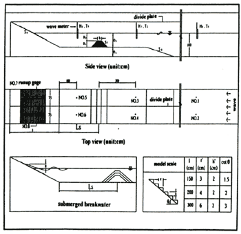
EXPERIMENT ARRANGEMENT
The experiment study was carry out in the wave flume of the Institute of Harbor and Marine Technology. The length of the channel equals 100 meters, the height 2 meters and the width 1.5 meters. The distance of the test model to the wave generator was 80 meters. Inside the test channel, a thin wood plate dividing the channel cross section into two portion was made. The width of both portion equal 0.75 m so that the wave runup height can be measured at the different dike style (for example the smooth and the step dike) simultaneously in the same incident wave condition. In front of the sea dike, there have a submerged breakwater was build up so that the influence of the submerged breakwater to the wave runup on the smooth and the step dike can be measured for analysis and comparison. The layout of the experiment was shown as in Figure 5. The incident wave height (Hs) is 4, 6, 8, 10, 12, 14, and 16 cm. The wave period that set on wave generator was fixed on 1.8 second. The side slope of the submerged breakwater was 1 to 1.5 (height to length) on both sides.
| (Enlarge: 55KB) |
 |
Fig.5 Layout of experiment
|