|
THE KITE TOWING SYSTEM
(ANTI-SYMMETRICAL TOWING SYSTEM)
Yutaka Terao1 and Takeo Nikko2
1Department of Marine Design and Engineering School of Marine Science and Technology, Tokai University Shimizu, Shizuoka, Japan
Seagull1@scc.u-tokai.ac.jp
2Imabari Shipbuilding Co., Ltd.
ABSTRACT
It is well known that the fishtailing instability or whirling motion occurs
when the ship is moored by single point mooring (SPM) system or towed with a single line. Whirling motion
is mainly introduced by the instability of the SPM or single line towing system itself, and worsens due
to the slack motion. We propose a new towing method and tested, named Kite Towing System (KTS) ( Terao
et al., 2000), which needs no additional special equipment. This paper shows the analysis of this
basic principle and results of numerical results using the newly developed simulation program. From this
model and numerical examinations, the stability of the towed hull motion by the Kite Towing System is
proved.
INTRODUCTION
If a ship is disabled to navigate due to troubles in engine system or others, it has been the common operation to tow the ship by other ship to a safe coastal area. When towing a ship, stern of the towing ship is connected to bow of the ship to be towed with use of a single towing rope. The towing ship tows the ship to be towed with the propulsion power of the towing ship. During towing a ship, a motion resembling to a swing of pendulum, is created in the yaw direction of the towed ship. This motion is called "whirling motion". This motion is also observed when a ship lies at its moorings.
The causes of generating the "whirling motion" are known such as the relationship
between ship speed and wind force, the shape of the bow of the ship being towed against the propeller
stream of towing ship, towing speed and length of towing rope ( Inoue et al., 1981,
Kijima et al., 1983). When a towing is recognized as the relative flow speed of the ship being towed,
the towing can be recognized as the phenomena that the mooring point such as mooring buoy is moving during
mooring. The effects of "whirling motion" on the ship being towed are as follows: 1. Problems affecting course stability of both ships
2. Increase of motion area of the towed ship by the "whirling motion"
3. Increase the load to the towing rope due to "whirling motion"
Effect (1) can be improved by elongated the towing rope. However, it may change
depending on the type of towing ship and on length of the towing rope. Effect (2) becomes a significant
problem when piloting a ship inside a bay or in a narrow water way because the motion area where a towed
ship swings around increases, since the distance between a towing ship and a towed ship is set to be longer
in many cases for safety reason. Effect (3) can generate a large stress (snap tension) momentarily on
a towing rope by the whirling motion and can rupture the towing rope or towing systems. It has been known
that these effects tend to appear significantly when towing a damaged ship ( Yuhara
et al., 1999; Kijima et al., 2000; Hara et al., 2000).
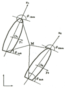
The methods to suppress the "whirling motion" have been investigated in the past. These methods need control energy, or adding resistive equipments. Even though these methods have been used, many accidents of rupturing the towing rope have occurred. Under such circumstances, we recognize necessity of developing a new towing method and mooring method that can suppress the "whirling motion" with simple facility. We have proposed the towing method called "Kite Towing System". As this name indicates, it is the towing system that makes use of the principle that a kite is stabilized in the air when it flies in an open air. If we can suppress the "whirling motion" and can obtain the course stability of ships with this method, we can open possibility of new towing method. We have carried out the towing test using simple model ships in 1998. From this test, we obtained the towing trajectories of towing ship and towed ship, and come to know that the "whirling motion" could be suppressed. Figure 1 shows the Kite Towing System (KTS) schematic view.
In the KTS, using only a single rope to moored point, and tow a ship with bow and stern rope makes practically no problem. However, if the sailing speed of towing ship increases by some, reasons, the retracting tension cannot be generated when a single towing rope is used. Because of this, using two towing ropes connecting both ships reduces freedom of motion of both ships, the towing ship and the towed ship, so that relative positional relationship between two ships can be maintained while both ships can turn around freely. In other words, connecting the two ships with two towing ropes like a kite can prevent the "whirling motion". In this method, directions of the bows of the two ships should be directed in an oblique direction towards outside each other. The two towing ropes are connected to the bow and stern of the towing ship. These two towing ropes are crossed each other once to form the towing condition. If difference of angle between the bows of these two ships becomes large, the towing resistance increases and is not desired. However, we place priority on suppression of the "whirling motion" to the resistance.
 Figure 1. Schematic view of Kite Towing System
Figure 2. Schematic view of the KTS balanced towing condition
If any trouble occurs, the towing rope connecting bow of the towing ship and stern of the towed sip can be disconnected to return simply to the conventional towing method.
In this research, we have investigated motions of both of the towing ship and the towed ship with KTS using numerical simulation. We have developed the maneuver motion equation of the two ships and created the hull motion calculation program using the maneuvering motion equation. We have made comparison between motion of the towed ship when it is towed by the conventional towing method and the motion of the towed ship when towed by KTS.
MANEUVERING MODEL
The Mathematical Model of Maneuvering Motion by KTS
Effectiveness of KTS in preventing the "whirling motion" is proved by the model
test. We have implemented the numerical simulation using the mathematical model (MMG model ( Hirano 1983; Kijima et al., 1992) of maneuverability to confirm the performance of preventing "whirling motion" by KTS.
The hydrodynamic forces that acts on vessel consists of ship type, propeller and rudder configurations while taking various motions in consideration. In addition to the above, the towing force effect is added as the external force term in KTS model. The external force that operates between the towing ship and the towed ship is only the towing rope force and the hydrodynamic force of mutual interference between the two ships is not taken into consideration.
The maneuvering motion equation can be expressed usually as shown below.
Where i = 1, 2 indicates that 1: Towing ship and 2: Towed ship. At the same time, (m1 + mxi) indicates the hull muss and apparent added mass in the x direction, and (m1 + myi) indicates the hull mass and apparent added mass in the y direction. (IZZi + izzi) indicates the hull and apparent added moment of inertia.
In addition, the external force that is applied to the hull can be expressed as shown below.
| Xi=XHi+Xpi+XRi+XTi (2) |
| Yi=YHi+YRi+YTi |
| Ni=NHi+NRi+NTi |
The subscript H, P and R indicate hydrodynamic terms that acts on the hull, propeller and rudder and T indicates the towing force by the towing rope. The term of interaction forces that are generated among the main hull, propeller and rudder, are included in this expression in addition to each of the hydrodynamic forces.
Hydrodynamic Forces That Act on Main Hull
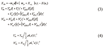
The hydrodynamic force that acts on hull can be expressed as follows.
| (Enlarge: 14KB) |
 |
Where Y'Hi and N'Hi are the dimensionless coefficients and can be expressed as follows. These motion derivatives are determined with the use of MMG's method.
Tension by Towing Ropes
In the KTS method, the two towing ropes connect the towing ship and the ship to be towed together. Where the force of towing rope connected to bow is expressed as Tfore_i and connected to stern is expressed as Taft_i・θfore_i and θaft_i that indicate angle between the hulls X-axis and towing rope. When the towing force is divided into the X-Y component, it can be expressed as follows.
| (Enlarge: 7KB) |
 |
Steady-State Balanced Conditions in KTS
We use the suffix i = 1, 2, which identified both hull, and assumed that both ships are sailing side-by-side with the forward speed U. When the ship 1 is assumed to be the towing ship and takes the orthogonal coordinates (ξ,η). The vertical axis ξ is taken same direction as U and the forces of the two ships in the x direction are balanced by the engine power of the towing ship as shown in Figure 2. The balanced forces in the h direction is expressed as follows;
The status of the ships going straight ahead in the ξ direction with forward speed U is maintained. Then, (βi) (j=1,2) are determined immediately. The positional relationship between the two ships during towing should satisfy the following Equation (7) when the moment NP generating the towing force T, cancels the turning moments of the two ships.
| (Enlarge: 13KB) |
 |
Where βi indicate the drifting angle, δi indicate the rudder angle and σi indicate the towing rope directional angle. Lx is the length up to the Yaw point of application of force. When the above relationship is satisfied, the relationship between the two ships can be maintained by KTS without using the turning moment that is generated by the rudder force. Moreover the rudder force can balance the deviation forces.
DESIGN OF THE KTS TRAJECTORY SIMULATOR
The numerical simulation model using the non-linear maneuvering model, proposed
by MMG is installed. Runge-Kutta-Gill method is used for the time step motion calculation. The towing
rope is assumed as a linear spring model for simplification of numerical calculation. When the initial
length of a towing rope is Tli_j0 and length of the towing rope after the time
t seconds is Tli_j , and also spring constant of the towing tope is Ki_j(j
= l: aft, 2: fore), the tension applied to the towing rope can be expressed by the following equation
(8). Calculated rope tensions are non-dimentionalized as Equation (9). Therefore negative towing force
means less towing force is calculated compared to the initial tension.

Our system is developed using Delphi 5 and developed simulator is shown is
Figure 3. The simulator initial conditions are given as a data file and used for
calculation. The rudder angle, simulation processing time, integration step-size and switching between
normal towing method and KTS can be entered with the use of GUI of window. Thus, the normal towing method
and KTS are compared so that suppression effect of the "whirling motion" by KTS is numerically proved.
At the same time, comparison of motion characteristics under different initial conditions such as length
of towing rope, etc., change of tension applied to the towing rope and change of fluid force acting on
vessel are investigated too.
The towing ship is assumed to be a bulk carrier and the towed ship is assumed
to be an ordinary cargo ship. Main principal dimensions are shown in Table 1. |