Proceedings of the Tenth (2000) international Offshore and Polar Engineering Conference
Seattle, USA, May 28-June 2, 2000
Copyright C] 2000 by The International Society of Offshore and Polar Engineers
ISBN 1-880653-46-X (Set); ISBN 1-880653-48-6 (Vol. II); ISSN 1098-6189 (Set)
Identification of Modes of VIV on a Drilling Riser from Measurements of Acceleration and Rate of Rotation
Karl E. Kaasen
Norwegian Marine Technology Research Institute AS
Trondheim, Norway
ABSTRACT
For analysis of measured VIV response within the Norwegian Deepwater Program (NDP) an estimator for riser displacements has been developed. The estimator uses information from of accelerometers and rotation rate sensors. Accelerometers mounted on a riser are sensitive to gravity due to the riser's angular oscillations. Neglecting this effect and doing double integration to obtain displacement may lead to results that have little similarity to reality, in particular for the low modes of vibration. The estimator overcomes this problem and is also capable of including measurements of rotation rate in a consistent manner. The principle of modal decomposition is used. A number of riser modeshapes are precalculated and the corresponding modal weights are found by least-squares estimation in the frequency domain. The estimator's sensitivity to sensor noise is studied and it is established that it is the influence of gravity that enables the accelerometers to detect modes oscillating at very low frequencies. The performance of the estimator is illustrated by an example. The effect of neglecting the gravitational "disturbance" is demonstrated.
INTRODUCTION
As a part of the Norwegian Deepwater Programme three drilling risers at sites outside the Norwegian coast were instrumented for measurement of vortex-induced vibrations (VIV). In addition to the measurements on the riser, the current was measured at a number of depths. The purpose of the instrumentation was to provide data for verification of theoretical models for VIV. This paper describes how the measurements of riser motion were processed to yield information that could be used in their verification. This information consisted of typically the lateral displacements of the riser along its length, the participating modes and their frequencies of oscillation.
In principle, the same method of analysis was applied to the data from all the three locations, although the instrumentation differed somewhat. The contents of this paper is based on the data from the Helland-Hansen site, as this riser had the most extensive instrumentation. The riser at Helland-Hansen was 683 metres long having a first natural period of about 36 seconds.
The instrument system to measure riser motion at Helland Hanssen consisted of six instrument containers attached to the riser in positions shown in Figure 1. Each container, numbered 1 through 6 from the bottom up, included motion sensors, data acquisition hardware and batteries. The main sensors were accelerometers for measurement of horizontal acceleration in two orthogonal axes, X and Y. In containers 3, 4 and 6 the accelerometers were supplemented with sensors for measuring angular velocity about axes X and Y. Further descriptions of the Norwegian Deepwater Program and analysis of VIV are given by Olufsen and Garside (1999), Halse (2000) and Kaasen et al. (2000). In the following we describe the task of calculating the modes of oscillation and lateral displacements of the riser from the records of acceleration and rate of rotation.
DISTURBANCE BY GRAVITY
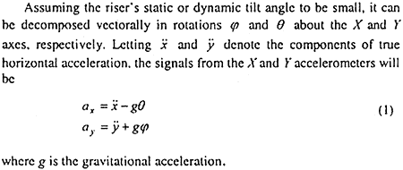
An accelerometer will measure true acceleration along its sensitive axis as long as the orientation of this axis is kept constant in space. In this case the projection of the gravitational acceleration on the accelerometer axis is constant and can be compensated for with internal circuitry or removed in the subsequent signal processing. For the accelerometers on the riser this will not be possible, as the motion of the riser at any point will be a combination of sideways motion and rotation. This will make the centreline of the riser deviate from the vertical causing the orientation of the accelerometer to deviate from the horizontal, thus exposing the sensing axis to the force of gravity.
For the following derivation, a set of orthogonal right-handed axes is defined. Axes X and Y are horizontal, whereas Z is directed upward. X and Y coincide with the axes of the sensors when the riser is vertical.

Figure 2 demonstrates the significance of disturbance by gravity. In the case of 1st-mode response of the riser the figure shows the frequency response characteristics of two accelerometers, mounted at positions L/4 and 3L/4 on the riser (L is riser length). It is clear that neglecting the effect of gravity and integrating the accelerometer signals twice to get displacement may lead to very erroneous results, especially at low frequencies.