2.4 Numerical procedure
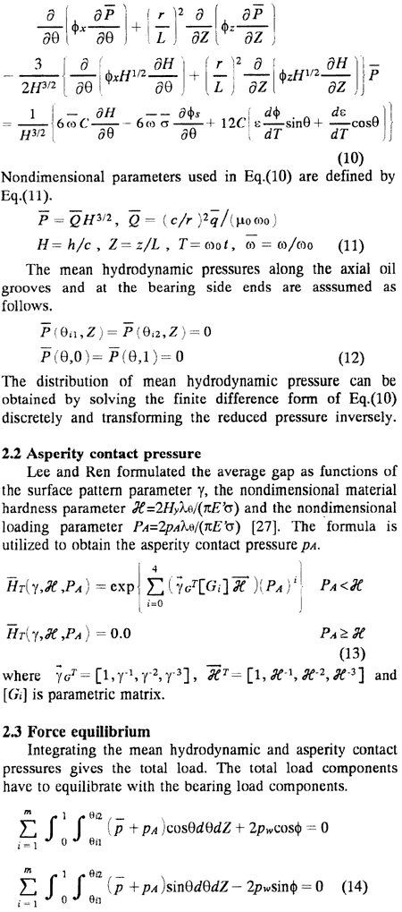
The numerical procedure to obtain the mean hydrodynamic and asperity contact pressures and the journal center locus from the above equations is summarized as follows.
(1) Initial values at an arbitrary crank angle are allotted to the position and the velocity of journal center. Equation(10) is solved numerically by a finite difference method using a successive over relaxation scheme. The asperity contact pressure is obtained from Eq.(13) by using a bisection method. The convergence of iterative method is achieved by an under relaxation method in the calculation of the elastic deformation of bearing liner due to the mean hydrodynamic and asperity contact pressures.
(2) The above calculations are performed repeatedly. The velocities dε/dt and dφ/dt are successively modified by the Newton Raphson method so as to satisfy Eq.(14).
(3) The position of journal center at a new crank angle can be obtained from the modified velocity components of the journal center by using the improved Euler method. These calculations are iterated until the journal center locus settles into a steady locus.
3. Calculation results and discussion
The mixed lubrication model presented in the previous section is applied to the crosshead-pin bearing in a two-stroke cycle diesel engine.
Fig. 1 Analytical model of crosshead-pin bearing
Fig. 2 Film thickness
Fig. 3 Changes in pw and (ω) with θc