4. ECONOMIZER EXPERIMENT
4.1 EXPERIMENTAL APPARATUS AND METHOD
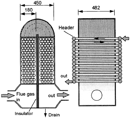
Shown in Fig. 15 is a schematic of experimental apparatus. The flue gas from a propane gas boiler is led to the lower plenum and flows upward and downward through the bank of tubes. The flue gas was released to atmosphere from the outlet plenum. Three kinds of countercurrent cross-flow heat exchangers, which consist of bare tubes, spirally finned tubes of fin pitch 5 and 10 mm, were designed and used for the experiment. The length of the bare and finned tubes was 482 mm. The temperature distributions of water and flue gas in the heat exchanger were measured with sheath K-type thermocouples of 1.6 mm in diameter. The thermocouple signals were transferred to a personal computer with a GPIB line and analyzed. The measurement error of the temperature in this study was within ±0.1 K. The pressure loss and the total amount of condensate generated in the heat exchanger were also measured.
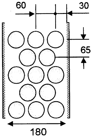
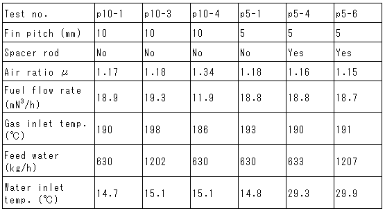
Shown in Fig. 16 is the arrangement of heat transfer tubes, The heat exchangers of finned tubes consist of staggered banks of 3-2 rows, 34 stages for the fin pitch 10 mm and 20 stages for the pitch 5 mm. The detail of the finned tube is already shown in Fig. 2. The outer and inner diameters of the base tube installed with the fins are 34 and 28.8 mm, respectively. The thickness and height of the plate fin are 1 and 12 mm, respectively. The parametric study varying the flue gas flow rate, feed water temperature and flow rate was conducted. The experimental conditions for the finned tube experiments are shown in Tables. 3. In a part of the finned tube experiments of fin pitch 5 mm, spacer rods of 23 mm in diameter were inserted in the tubes to increase the water velocity.

Fig. 15 Schematic of experimental apparatus

Fig. 16 Arrangement of heat transfer tubes
Table 3 Test conditions of finned tube

Table 4 Composition of Propane gas fuel

4.2 EXPERIMENTAL RESULT AND PREDICTION
4.2.1 Temperature distribution in bank of fin pitch 10 mm tubes
Shown in Fig. 17 is the comparison of experimental result and one-dimensional prediction for the bank of fin pitch 10 mm tubes. The outer wall temperature for the finned tube depicts the outer wall temperature of the base tube where the fins are welded. As it was difficult to avoid the falling condensate on the thermocouples in the finned tube configuration, the thermocouple signal sometimes indicated the lower temperature than the actual gas temperature. The scattering of the gas temperature is considered to be due to the wet thermocouples. The gas temperature locally rises as much as 20℃ at the middle of the bank where the gas flow becomes the down-flow from the up-flow. It is considered that the thermocouple indicates the correct gas temperature at the middle position as it locates enough above the condensing bank. It should be noted that the measured gas temperature with the dry thermocouple agrees well with the predicted gas temperature. The general temperature profiles can be predicted well with the one-dimensional mass and heat balance calculation.
The above mentioned study for the single stage showed that the condensate flowed downward and re-evaporated on the lower part of fin. It is possible that the re-evaporation takes place more frequently in the multiple stage as the condensate generated at the upper stage falls down on the lower stage. The re-evaporation decreases the net heat flux from gas to water. So the parametric calculation for the fin efficiency was conducted. When β=5 was used in the Eq.(21), the fin efficiency became approximately the half of that at β=1 at the condensing region. However, the significant difference could not be observed on the general behavior. The lower fin efficiency decreases the outer wall temperature of the base tube welded with fin. So the condensation heat transfer coefficient increases significantly with the decreased wall temperature. As the result, the net heat flux from the gas to the water can not be affected significantly with the fin efficiency in the condensing region. In the non-condensing region, the heat transfer coefficient is not affected with the wall temperature and the net heat transfer decreases significantly with a decrease of the fin efficiency. It is considered that the degraded fin efficiency in the condensation region does not have a strong effect on the general calculation result.
BACK CONTENTS NEXT