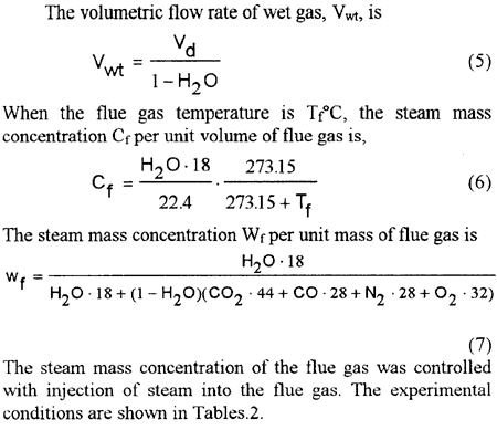
Fig. 3 Predicted and measured dew points
丂
3.2丂HEAT TRANSFER CALCULATION OF FIN
The inner wall temperature of the polycarbonate test section was 85亷 as a maximum, The contribution ratio of the radiation heat flux from the inner wall to the test tubes was within 5%, of the total heat flux qT When the emissivity of the polycarbonatc wall and the tubes covered with the condensate were assumed as 1 . As an accurate estimation of the radiation heat transfer is difficult, it was neglected in the following analysis. The total heat flux qT consists of the convection heat flux qV and the condensation heat flux qC as
qW = (qV + qC)(AB + AF兣)/AW丂(8)
where AW is defined as the heat transfer area when the fin height is 0. In the experiments, qW was obtained from the temperature difference and flow rate of the cooling water. The convection heat flux is expressed as
qV = hV (Tf - TW)丂(9)
The condensation heat flux qC can be expressed as,
qC = hCLW(Cf - CW)丂(10)
The following empirical correlation [4] was available in the range of 2 亊 103 亙 Ref 亝 5 亊 105
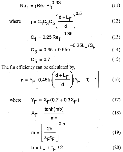
The fin efficiency strongly depends on the heat transfer coefficient, h, in Eq.(19). These correlations were obtained from the single-phase experiment where the heat flux is a simple multiple of the constant heat transfer coefficient and the temperature difference between wall and fluid. Although the condensation heat flux can not be expressed with the above simple relation, it is considered that the Eq.(19) with the larger heat transfer coefficient taking account of the condensation heat transfer would give an approximation. As a first attempt. the following equivalent heat transfer coefficient in the condensation region was used.
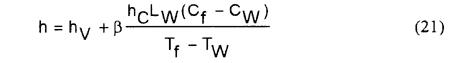
wher 兝=1 for the usual calculation.
丂
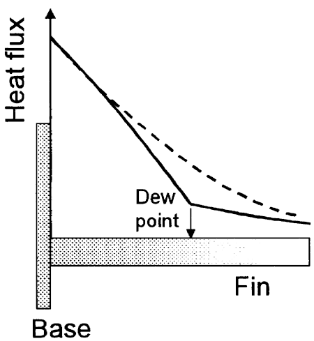
Fig. 4丂Approximation of heat flux distribution