The compatibility of results is checked by changing the length of reaches.
The bottom figure shows the pressure transients at the downstream of the valve ((A) in Fig.2) and at the beginning of the sea bottom line ((B) in Fig.2).
When the oil head of shore tank is higher (Fig.3 (a)), the oil in the pipeline begin to flow inversely earlier after the valve closure due to higher head, so friction loss during the growing and collapsing process of the cavity is smaller. Therefore, in the case of Fig-3 (a) the initial momentum energy is preserved more and the magnitude of waterhammer pressure rise is larger compared with the case of Fig.3 (b).

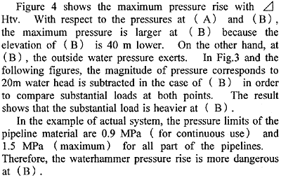
In the example of actual system, the pressure limits of the pipeline material are 0.9 MPa (for continuous use) and 1.5 MPa (maximum ) for all part of the pipelines. Therefore, the waterhammer pressure rise is more dangerous at (B) .
In the case the pipe is damaged at (A) by waterhammer, it would be relatively easier to cope with because it is on the berth and there are other valves to cease the oil spill. However, in the case the undersea pipeline is broken, it would become much serious oil spill accident. The oil included in the undersea pipeline is 10,000 - 20,000 m3.
The waterhammer is serious if it occurs when the shore tank oil head is large, or flow rate is large. Mostly, the flow rate automatically decreases along with the increase of the shore tank oil head, according to the pump performance. In the case the tank is mounted at relatively high elevation or the tank is designed to hold oil up to a relatively high level, the flow rate should be paid attention in order to prevent an unexpected accident.
3.2 Break-line mode valve operation and pressure transients in sudden coupler detachment
It is known that the break-line mode valve operation is one of the effective valve operations to suppress the high pressure rise of waterhammer or avoid the column separation. Figure 5 shows an example of valve stroking.
With the valve operation shown in the top figure, no vaporous cavity is produced and the pressure rise is kept low.
These valve operations require a certain time duration. Sometimes the ship movement might be unexpectedly fast or the emergency operations are delayed for some reasons.
Figure 6 (a) (b) shows the pressure transients when the coupler is cut off before the valve is closed completely. In this case, the isothermal change of the air inside the pipe is assumed.
In the case of Fig.6 (a), the valve is closed according to the break-line mode operation until it is completely closed.
On the loading arm side, air flows in through the unclosed valve after the detachment. When the valve is closed, some amount of air is trapped near the valve. The waterhammer pressure rise is suppressed by the air. There is little oil spill through the valve because the air cavity occupies the opening part until the valve closure.
On the ship side, oil spills through the valve. The middle figure shows the prediction of the amount of oil spill. On this side, the valve operation programmed in advance should be cancelled and the valve must be closed immediately after the detachment.
Fig. 4 Maximum pressure in the pipeline
Fig. 5 Pressure transient at break-line mode valve operation
Figure 6 (b) shows the case where both sides of the valves are closed immediately after the detachment. In this case, the pressure on the loading arm side rises higher compared with the case of Fig.6 (a) because almost no air is trapped.
Figure 7 shows the comparison of results in the case either the isothermal change or adiabatic change of the air is presumed for the same case as Fig.6 (a). In the figure, when the pressure rises after the valve closure, the pressure of the adiabatic change goes up earlier. In the case of the adiabatic change (PVk=const), the pressure should increase rapidly for the same volume decrease.