2.6 Basic Assumptions
2.6.1 Base Time
The base time of consideration of the welding effects is the time at the end of the cooling cycle where the temperature and the deformation of the welded assembly do not change any more.
2.6.2 Mechanism of Welding Distortion
The final distortion of the welded assembly is resulting from the deformations in three main thermal zones during two cycles heating and cooling; this means that the origin of distortion of the welded assembly would come from the difference between the dilatation state (in heating cycle) and the contraction state (in cooling cycle) of the metal during two thermal cycles. Therefore, executing in the same welding conditions on the identical workpiece, we would obtain the same results:
- the identical fusion zone FZ (in surface and volume),
- the identical heat affected zone HAZ (in surface and volume),
- the identical non heat affected zone NHAZ (in surface and volume),
- the identical induced welding effects (stresses and deflections).
2.6.3 Sizes of Thermal Zones
The sizes of three thermal zones, limited by their peak temperatures (Tf, T.c Ta, T0) occurred in the heating cycle, are determined by the following Adam's formula [6]:

where:
y = distance (in mm) of the given point from the fusion zone centre or from the front of maximum temperatures
Tp = Peak temperature at the given point (in ℃)
e = base of natural logarithms
= 2.718
t = thickness of workpiece (in mm)
Note: For calculating the limit y of :
- the FZ : Tmax = Tf and Tp = Tc
- the HAZ : Tmax = Tf and Tp = Ta
2.6.4 Excessive Deflections of a Welded Plate
The excessive deflections of a welded plate are due to the buckling state of the plate when the contraction forces developed in the weldment overpass the effective buckling limit of the plate, i,e. of the NHAZ of the welded plate.
2.6.5 Effective Buckling Limit of a Plate
The effective buckling limit of a plate is considered as the effective capacity of its resistance against the buckling compressive force, taking into account all the residual states accumulated into the plate during all the preparation works such as cutting, rolling, planning... before welding assembly operations [9] and it is evaluated by the modified Euler-Bryan formula as below [3]:

where:
Kc = corrector coefficient estimated to be (0.8<Kc<1)
β = Brayan's coefficient depending upon the ratio (a/b), the boundary conditions and the mode shape of plate
a, b, t = length, width and thickness of plate (in mm)
E = Young's modulus of plate material (in N/mm2)
v = Poisson's ratio
In shipbuilding, for deck and bulkhead assemblies, the plates of stiffened panels are generally assumed under one of these two cases of boundary conditions:
Case 1 : Plate with all edges supported
Kc = 0.8
β=4 (for a/b > 3)
Case 2: Plate supported with one free edge alongside
Kc = 0.8
β = 0.5 (for a/b > 5)
2.6.6 Effective Peak Temperatures Distributions
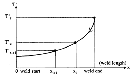
The cooling cycle starts up soon after the solidification time St Of the melt metal in the fusion zone, so that at any point in the workpiece, the effective temperatures are then dropped down to a lower level by the cooling rate effect during this very short time: T'p = Tp - R(Tp).St
The effective peak temperatures (T'f, T'c, T'a)applied on the limit weld line of three thermal zones are calculated from the end to the start of the welding operation by the relation below Fig.4:


Fig. 4 Distribution of Effective Peak Temperature on the Weld Line of a Thermal Zone
2.6.7 Effective Shrinkages in Three Thermal Zones
At the end of the cooling cycle, the effective shrinkage values in three thermal zones are resulting in:
α (NHAZ) = α (ferrite) - α (ferrite) = 0
α (HAZ) = α (ferrite) - α (austenite)
α (FZ) = 0 - α (austenite)
2.6.8 Elastic Domain
As the non heat affected zone NHAZ which represents the largest part of the welded assembly, has no change in its physical and mechanical properties before and after welding process, it is assumed to be submitted to the Hooke's law and so it is only considered in the calculation results.
2.6.9 Idealization of Weld Joint Sections
Two of the most used weld joints for fabrication of stiffened panels are Fillet and V butt welds. For both weld joints, their sections are simplified and idealized into the perfect triangular sections of weld deposit metal (for simple and multipass welds). These idealized sections are assumed to be constant along the weld line (Fig.5a and 5b).