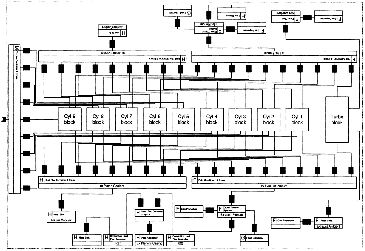
Fig. 9: Building block representation of the Diesel engine.
丂
Due to space limitations the inlet port, the exhaust valve and the heat transfer of the cylinder blocks are not presented. The cylinder model is connected using an angle changer element with the crankshaft. The angle changer element provides the phase angle change for each cylinder. The angle changer element is connected with the piston geometry element which translates the crankshaft rotation to piston motion and provides with the necessary data (volume, volume change rate, piston position, piston velocity) to the open thermodynamic system element and translates the gas pressure applied to the piston to torque developed (or absorbed) to the crankshaft.
The model was implemented using ACSL (Advanced Continuous Simulation Language) and runs on a PC.
丂
3.1 Steady State Results
Here the steady state results of a single cylinder of the engine are presented. The results are for 100% load at 95. rpm and are presented versus the crank angle position. The results are compared with the data provided from the engine manufacturer for a single cylinder for the same load and rotational speed.