3. EXAMPLE
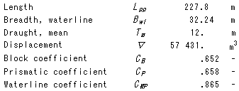
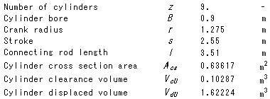
Here a brief presentation of modelling a container ship equipped with a Diesel engine is presented. The main dimensions of the container ship are presented in Table 1 while the main dimensions of the propeller are presented in Table 2. The container ship is equipped with the MAN-B&W 9K90MC MkVI Diesel engine for which the main dimensions are presented in Table 3.
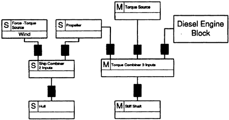
The building block representation of the ship is illustrated in Fig. 7. The ship consists of the hull, the propeller, the wind (modeled using the force-torque element), a generator (using a mechanical torque source element) and the Diesel engine block.
Table 1 : Main dimensions of the container ship

Table 2: Dimensions of the propeller

Table 3: Dimensions of the MAN-B&W 9K90MC MkVI Diesel engine


Fig. 7: Building block representation of the ship.
The building block representation of the diesel engine is illustrated in Fig.9. The engine consists of an array of 9 cylinders. Each cylinder is equipped with two fluid interfaces (one from the port and the other from the exhaust valve), two heat interfaces (for the jacket and piston coolants) and one mechanical interface which provides the torque developed from the cylinder. The turbochargers block includes the 3 turbochargers of the engine. A mechanical combiner combines the mechanical outputs of the cylinders to one equivalent to be connected to the crankshaft. Two fluid combiner elements combine the fluid of the cylinders and the turbochargers and connect them with the inlet plenum and exhaust plenum respectively. Finally two heat combiner elements combine the heat rejected from the cylinders allowing the use of a single coolant model for all cylinders. The engine block is cooled by two different coolants, the first is cooling the jackets and the head (jacket coolant) and the second is cooling the pistons (piston coolant).
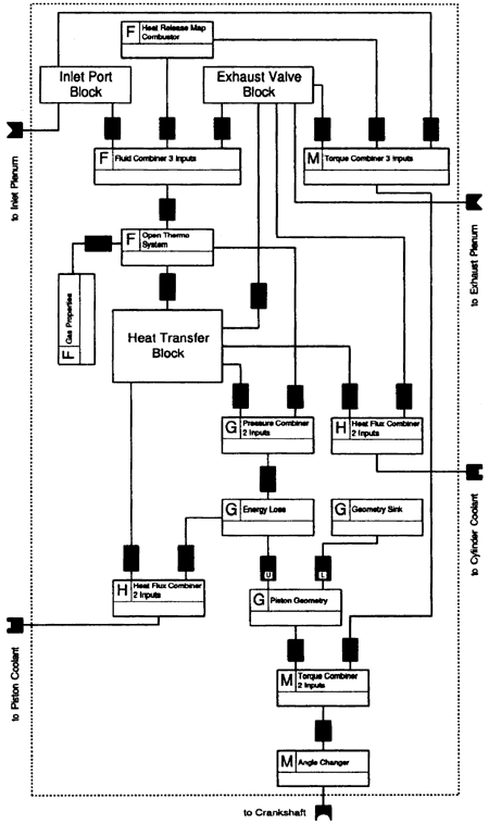
The building block representation of a single cylinder is illustrated in Fig. 8. Since all cylinders of the Diesel engine are considered identical (except for the phase angle) only the model of one of the cylinders is required (the others can be copied changing only the phase angle for each cylinder).

Fig. 8: Building block representation of the engine's cylinder.
The center element of the cylinder, is the open thermodynamic element which models the working fluid in-side the cylinder. The open thermodynamic element is connected with the gas properties calculation element which provides the thermodynamic properties of the gas inside the cylinder. The open thermodynamic system element is connected (via a fluid combiner with 3 inputs element) with the inlet port, the exhaust valve and the combustor.
BACK CONTENTS NEXT