c) Room data
There are several kinds of specifications of the interior usually. Rooms are divided into one of these specifications according to its layout and type. Therefore, it can become easy by the use of the standard spec. Table to input the specification of the each room. The kind of the standard spec. tables which is implemented by using the Access2000 are as follows:
c-1 Loss factor of the room
This is the factor to represent the energy dispersed in the element, the quantity of which is proportional to the energy kept in the element in charge. These value is determined every octave band according to the result of the measurement carried out by NK.
c-2 Material
This is the data which includes density, Young's modulus. Poisson's ratio for each material of the floor, wall and ceiling. This data also includes the loss factor every octave band.
c-3 Wall
This is the data which includes the material code mentioned before and the thickness of the plate.
c-4 Room
This is the data which includes material codes of the floor, the ceiling, the wall and the interior, and the room loss factor with the magnification.
丒Coupling loss factor
This data expresses the ratio of the energy transmitted between two adjacent elements, which depends on the frequency and the characteristic and size of the material. Values in this table are based on the calculation of the theoretical equation. The coefficient which is used when this factor is applied is modified according to the equation presented by HATTORI [6] which considers the effect of the reinforcement welded at the edge of the steel plate in the hull structure [5], [7], [8]. This table includes two types of the loss factors which correspond to the accommodation space and the machinery space respectively.
丒Sound Sources
The data of the sound source is determined from the result of the field measurement. Following data is prepared at now.
i) Data of the sound power of 8 types of the main diesel engines and 12 types of the auxiliary engines
ii) Data of the sound pressure and the acceleration around the engine including the engine bed which is obtained from the measurement at the sea trial (6 cases).
In the calculation of the estimation, the data of these sound sources is given at the position of the main engine or the auxiliary engine respectively.
丂
4.2.2 KNOISE Solver
If the construction of the hull structure, the arrangement of the room include machinery spaces and the sound sources are given, KNOISE calculates the sound pressure levels and the acceleration levels of all elements in the calculation model. The result of the acceleration calculated is represented by the converted value into the "sound temperature level" (hereafter, refereed to "STL").
The outline of STL is as follows; In generally, while the air borne noise is expressed in SPL (sound pressure level), the structure borne noise is expressed in L兛 as equation (4), (5). Because they have no common physical meanings to each other, it is difficult to know the energy flow among elements. However if the acceleration is expressed in STL unit, it can be directly compared with the sound pressure because STL is equivalent to SPL. STL can be easily calculated [6], [9].
where,
p: sound pressure (pa)
p0: reference sound pressure = 2 x 10⁻⁵(pa)
兛: acceleration (m/s2)
兛0: reference acceleration = 1 x 10⁻⁵(m/s2)
丂
4.2.3 KNOISE Postprocessor
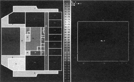
As the result of the calculation, the list of the data and the figure which shows the distribution of the noise level of each layer can be displayed on the screen of the personal computer. The detail is expressible by zooming up each cabin as Figure 3. Moreover, the function to split one screen into two screens is implemented. When the specifications of a part of elements is changed because of some reasons, the comparison between two results of pre and post change respectively can be visually carried out using this function.
丂
As for the other function, the comparison between the result of the measurement and the result of the calculation with the parameters necessary for the calculation can be reflected in the system. To assist this work, there is a function to express the difference of these two results in the graph and to display the sound energy flow among the elements. With this, various functions for the display and the print are prepared at need.
丂
5. APPLICATION OF COMPUTATION TO THE SHIP AT THE DESIGN STAGE
丂
5.1 Outline
Several studies have been made on the prediction of the ship noise using the SEA theory. The purpose of these studies is almost to examine the possibility of the implementation and the application of the program. Therefore, the calculation is not necessarily carried out before the measurement. It seems that the calculation in this manner can't be used as the prediction because the prediction must be carried out at the design stage before the construction of the ship. The goal of KNOISE is to realize the prediction at the design stage. As mentioned before, the parameters for the calculation are necessary.
Therefore, the experimental values obtained by many experiments are used in KNOISE. However, these values are not necessarily obtained in all cases. In these circumstances, it seems to be reasonable that the calculation of the prediction ought to be carried out according to the following plan:
1. In the case that there are parameters of the sister ship of the ship to be calculated or the similar ship which has the same specifications of the accommodation space as the ship to be calculated, the calculation should be carried out using these parameters.