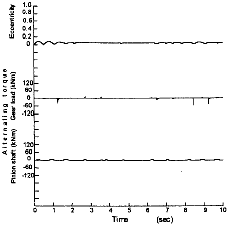
Fig. 5 Calculated waveform(point considering backlash)
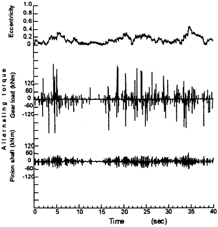
Fig. 6 Calculated waveform (point considering backlash)
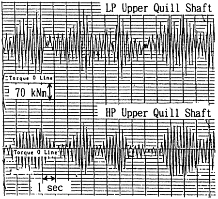
Fig. 7 Measured waveform of shaft torque
And also the calculation results clearly indicate the significant difference in waveform between the case with backlash and without backlash, especially near the boundary line of unstable area. The severe fluctuation of the alternating torque is calculated as shown in Fig. 6. This is reproduced only when both gear backlash and oil film is taken into consideration and closely resembles the waveform as shown in Fig. 7. This is the waveform of the alternating torque of the pinion shaft actually observed in the steam turbine vessel in astern operation around 50 rpm, of which the calculated unstable rpm is 51 rpm by the proposed method.
This implies the causes of the fluctuation of the alternating torque, i.e., the stable area is not fixed but varies with the spring constant depending on the amplitude of the vibration in such non-linear vibration, as includes backlash in the system.
4. CONSIDERATION FOR UNSTABLE PHENOMENON
As shown in Fig.8, the lateral movement of the journal can create the coupled vibration with the torsional vibration by the rotating motion about the contact point of the gear tooth which results in twisting the shaft. Then, the shafting with a reduction gear supported by the plane bearing always has possibility to suffer from the unstable coupled vibration of the self-exiting vibration of the bearing and torsional vibration. It appears especially for the case that there is an operation with low load on the gear in a normal operation range.
Therefore, when designing the shafting with torsional vibration problems, the operation point should avoid the unstable area of the self-exciting vibration coupled with torsional vibration. But it is not practical for the designer to calculate the unstable area by solving the characteristic equations of the coupled vibration or by the computer simulation considering the gear backlash especially for the system with large degrees of freedom.
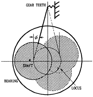
Fig. 8 Steady oil whirl model
BACK CONTENTS NEXT