All these conclusions allowed us to the elaboration of an approximate quasi-steady analytical method presented below.

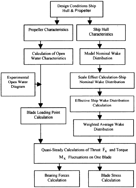
Fig. 3. Flow-chart of Propeller Excitations.
1.2. The analytical method
This model is based on the same lifting line theory, but using the propeller vortex model: the j-th blade will be substituted by a line of bounded vortices which interacts with a filament of free vortices (Fig. 5). An arbitrary point P was taken on an element situated on the filament of free vortices, in the cartesian and cylindrical coordinates. The absolute velocity in this point in results from Figure 1:

ω being the blade circular velocity. The correlation between the modules of these vectors and the corresponding angles, for a blade element situated at radius r is given by:

where the water velocity V* through the propeller disc was calculated by means of the mean value of the wake coefficient, estimated with empirical relation [1], [6], [7] taking into account the overall dimensions of a concrete 55,000 tdw bulk carrier having a four-bladed propeller with a diameter D = 6.4 m. The induced velocities may be written, starting from the Biot-Savart formula, as:

with Γthe circulation; the integrant Lerbs coefficients are:

and from here, using the notations:

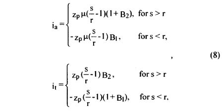
the coefficients from (8) may be expressed [8], [9], [10] by asymptotic approximation, as follows:

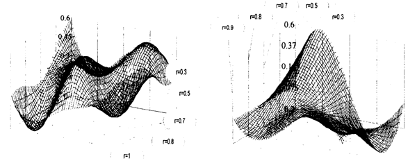
Fig. 4. Variation of the Axial Wake (left) and Tangential (right) w(r, θ) Velocities versus Rotation Angle and Blade Radius.
BACK CONTENTS NEXT