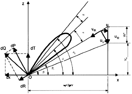
Fig. 1. Schedule of the Quasi-Steady Method.
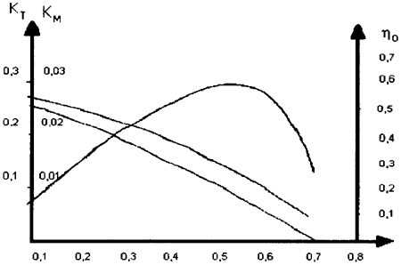
Fig. 2. Loading and Open-Water Efficiency Distribution along Blade Radius.
1.1. The semi-analytical method
The quasi-steady method assumes that the characteristics of a propeller in each phase of unsteady motion are approximated by those in uniform flow at the same phase. Thus, if the non-uniform flow field is known around a propeller from experiments, the flow speed and the angle of attack at each phase are easily calculated according to the diagram represented in Figure 1. The propeller characteristics at each phase of the unsteady motion are obtained either using the lifting line theory which gives loading distribution (dKT / dr, dKQ / dr), shown in Figure 2, along the radius, or considering the total blade loading calculated from the experimental open-water characteristics of the propeller. which is to be distributed along the radius using weight functions as recommended in [1] J or [2]・ Using the first variant, the radial application point of the resulting forces on the blade can be accurately calculated by integration along the radius. Considering the blade at an instantaneous angular position θ, for a blade element dr situated at radius r, the instantaneous values of thrust and torque generated by the blade element are easily calculated as follows (the flow-chart from Figure 3):
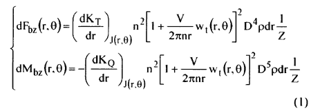
where the wake velocities w(r, θ) are determined experimentally (Fig. 4). D being the propeller disc diameter, n its speed and J(r, θ) the instantaneous advance coefficient. The other components of forces and moments on the propeller shaft can be written as:
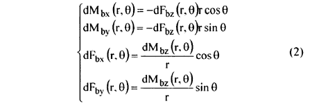
At each phase the force and moment components acting on the whole blade are calculated by integrating between hub and blade tip, having as radia Rh and R, respectively:
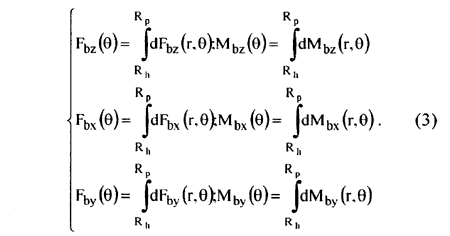
The total periodic forces and moments acting on the whole propeller at each phase are the sum over all Z blades. They are often presented as amplitudes and phases of the blade harmonics:
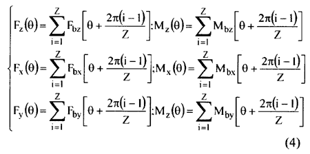
The whole calculation process of propeller torque and thrust (so-called bearing forces) by this semi-analytical quasi-steady method is presented through the flow-chart shown in Figure 3.
In order to validate this mathematical model, comparison with some specialized computer codes [3] have been made [2], [14]. The resulting thrust fluctuation on one blade show a good correspondence between several programs, made by different authors. All these systematic comparisons lead to the following division of the trend research in the field: (i) unsteady lifting surface theory (so called the exact method); (ii) approximate theories for unsteady flow; (iii) quasi-steady theories. Some conclusions must be here mentioned;
・ the effect of velocity tangential components on the unsteady blade loading is small:
・ a blade force amplitude scattering of about 25% at low harmonic orders were reported between similar exact calculation method;
・ the spreading of results of results for unsteady thrust and torque at blade frequency. calculated with methods (i) and (iii), is about 30÷35% with respect to the experimental values [4]. whereas the one obtained from calculations with methods (ii) is even more higher;
・ it seems to be of little practical use to improve the exact theories, since the quasi-steady methods give very good results for the lower harmonic orders; probably these methods are the best practical solution for the unsteady propeller blade forces calculation.
BACK CONTENTS NEXT