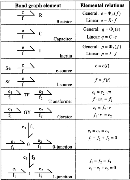
Figure 2. Bond graph elements.
丂
Using these basic elements, a graphical model can be constructed of a system. It is a remarkable fact that models based on apparently diverse branches of engineering science all can be expressed using the notation of bond graphs. This allows one to study the structure of a system model. The nature of the parts of the model and the manner in which the parts interact can be made evident in a graphical format. The resistor, capacitor and inertia elements are used to model passive elements in the various energy domains. The resistor, which relates the effort to the flow on its single bond, is often constrained to dissipate power only as an electrical resistor or mechanical dashpot would. The inertia and capacitor involve the energy variables, p and q, and store energy. In mechanical systems, the I-element represents a mass and the C-element a spring.
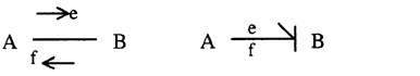
The transformer and gyrator 2-port elements are usually shown with a "through" sign convention takes the form
f1丒f1 =e2丒f2 丂丂丂丂丂(5)
where the numbering of the bond provides a convenient way to identify e, f, p and q variables. In mechanics, the TF element represents lever and gear ratio and the GY represents gyroscopic coupling.
Perhaps Paynter's major innovation in inventing the bond graph formalism was to represent interconnection laws as power conserving multiport elements. In mechanics, the laws go by the name of "geometric compatibility" and "dynamic force balance" while in electrical circuit theory the corresponding laws are called the Kirchoff current and voltage laws.
The 0- and 1-junction elements are shown in 3-port form although n-port version is often used by an obvious extension of the constitutive laws given in Table 1.
In mechanics, if three 1-ports are bonded to a 0-junction, the forces are all equal. This means that the 1-port elements are in mechanical series. If the elements are bonded to a 1-junction, velocities are common and the elements are in mechanical parallel.
Using bond graphs, the differential equations can be constructed in an algorithm manner from the graph. That is the graph is perfectly equivalent to the differential equations of the form

with state vector, x, and input vectors u. The state equations can thus be written unambiguously in an algorithmic way. However, before the equations can be written from the bond graph, causal information must be added to the graph. Causality means obtaining an explicit indication of which variables for an element is to be considered independent and which are to be considered dependent. Said another way, which are the inputs and which are the output variables. The problem of assigning a particular causality to a system model is related directly to the manner in which the system can be simulated, or the manner in which the system equations can be written without difficulty. The way both the effort and flow signals travel are indicated directly on the graph by drawing a perpendicular line at one or the other end of the bonds.
The simultaneously representation of physical and computational structure is a unique and very powerful property of the bond graph which other representations like the linear graph or the block diagram do not have.
丂
6. COMPUTER MODELLING AND SIMULATION ENVIRONMENTS
丂
As was mentioned previously the use of the computer as an aid to the difficult process of abstracting a physical reality to a mathematical model is a must if simulation is to have a prosperous future. When using the bond graph modelling method, the representation ends up as a graphical topological structure of the system consisting of power bonds and basic elements shown in Figure 1.
The derivation of differential equations from an augmented bond graph follows an organized pattern and well established rules, and it should be possible to use software logic to generate the model description directly from the computer screen. Software that assists model building could be extremely useful and a break-through in utilization of the simulation technology in the future.
Looking at the use of simulation as a tool from an industrial point of view, the added value from using simulation is the use of the model to analyse the problem at hand.