Fig. 8. Compressor performance map.
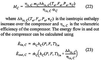
The torque required for the compressor can expressed as

where the last term in the second line of Eq. (23) is the enthalpy difference over the compressor.
The input data required for the compressor model are in addition to the compressor performance map as shown in Fig. 8, the volumetric efficiency as a constant or a function of pressure ratio.
In order to handle compressor surge and stall a procedure for extrapolating the performance map is implemented. This extends the turbocharger model to although not perfectly accurate, handle large transients in a consistent way.
Complete turbocharger model
The turbocharger rotor connecting the turbine and compressor can be represented as a common speed 1-junction. The inertia and mechanical friction of the rotor are added using I and R elements respectively. The input data necessary for the rotor model is the rotor inertia JT, and mechanical efficiency.
The complete turbocharger model consisting of the turbine, the compressor and the rotor models are shown in Fig. 9. Due to our use of predefined tables and relations, the causality of the total model are fixed. This does not normally represent any problem, because the turbocharger always is connected to component models upstream and downstream that solves the causality conflict normally experienced.
Fig. 9. Bond graph model of turbocharger.
4.6 Exhaust system
The exhaust system of a modern diesel engine is designed basically based on two approaches. In engines with constant pressure turbo charging the manifold are designed as a large single volume, the exhaust receiver, aiming at reducing the pulses from the individual cylinders before entering the turbocharger turbine. From the cylinder to the exhaust receiver pipes with increasing area are however often found. The exhaust system for this kind of systems can often be modeled as a large singe volume, neglecting effect of the short pipes. A little more realistic model is to include the pressure waves in the pipes leading up to the large exhaust receiver volume. For engines with pulse turbo charging systems, the added momentum from exhaust gas when expanded into the exhaust system is utilized and lead directly to the turbocharger through a pipe network designed to reduce negative interaction from other cylinders. These kind of systems have to be modeled using wave-action models.
In [18] a model based on the solution of the one-dimensional gas dynamic equations is developed. Based on the conservation of mass, momentum and total energy a model is developed from a control volume and method of lines approach. The model is easily interpreted in a pseudo bond graph notation. The model is found extremely robust and accurate for a large number of applications. However the model does not handle the case where the composition of the exhaust changes along the pipe segment.