Fig. 1 The 9 basic bond graph elements
The problem of assigning a particular causality to a system model is related directly to the manner in which the system can be simulated, or the manner in which the system equations can be written without difficulty. The way both the effort and flow signals travel are indicated using causal strokes on the graph by drawing a perpendicular line at one or the other end of the bond, as shown in Fig. 2.
Fig. 2 Causal information in bond graphs.
The simultaneously representation of physical and computational structure is a unique and very powerful property of the bond graph which other representations like the linear graph or the block diagram representations do not obviously have.
Modeling thermo-fluid systems
In order to model a general multicomponent gas phase control volume system, the classical bond graph method can be extended to a multiple bond representation known as the pseudo bond graph concept [7] [8].
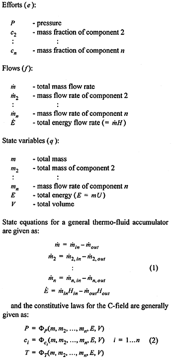
The efforts, flows and state variables for the pseudo bond graph concept for modeling multicomponent gas phase systems, are as proposed in [9]:

The actual relations to be used for evaluating the constitutive laws of the element depends on the assumed properties of the fluid, i.e. if the fluid follows a perfect gas law, an ideal gas law or a real gas law. The model is also capable of predicting two-phase equilibrium systems [9].
Fig. 3 Pseudo bond graph model for a multicomponent fluid accumulator