丂
(5) Auxiliary boiler control system operation
The trainee can operate the local panel of the auxiliary boiler as simulated engine mom on the ER operator station CRT. For example, start or stop forced draft fan, fuel pumps, monitoring and emergency shutdown.
丂
4. SIMULATION PLANT MODEL CONFIGURATION
丂
The simulator has precise simulation plant models and is designed on the basis of operation know-how of a large modern container ship coming from the design data that can be stored only by the manufacturer of main diesel engines, propulsion machinery, stealing gears and plant engineering.
The mathematical plant model of the simulator is based on the physical conception of the behavior and characteristics of the plant. The internal condition (flow, pressure and temperature) of each element (pipelines, valves, tanks and main and auxiliary machineries including heat exchangers) in the plant is calculated on the basis of heat balance, mass flow balance and boundary conditions.
丂
4.1 GENERAL
The mathematical model of the simulator is based on the physical conception of the behavior and characteristics of the plant. The model is constructed by a module according to each function.
This plant has the following features;
(1) Single engine propulsion plant with fixed propeller
(2) Single-acting two-stroke, slow speed, large bore, crosshead type diesel engine with uniflow scavenging
Engine model; Mitsubishi-Sulzer 12RTA 84C
(3) One stage, constant pressure turbo-charging system with intercooler
(4) Lubricating oil system as coolant to; main bearings, pistons, turbo-chargers, etc.
(5) Central cooling fresh water system as coolant to; 3 main engine air coolers, 2 main engine L.O. coolers, 1 main engine turbo-charger L.O. cooler, Main engine cylinder jacket, 4 diesel generator engines, 3 air compressors, etc.
(6) Cooling sea water system as coolant to; 2 C.C.S. cooling fresh water coolers, 1 jacket cooling fresh water cooler
(7) Steam generating plant consisting of; 1 exhaust gas economizer, 1 oil fired auxiliary boiler connected to the exhaust gas economizer.
(8) Steam consumers; 2 fuel oil tank heaters, 2 main engine fuel oil heaters, 2 generator engine fuel oil heaters, 7 purifier heaters, etc .
(9) Four diesel engine driven generator sets
(10) Electrical consumers; electrically driven pumps, air compressors, ventilation fans, etc,
丂
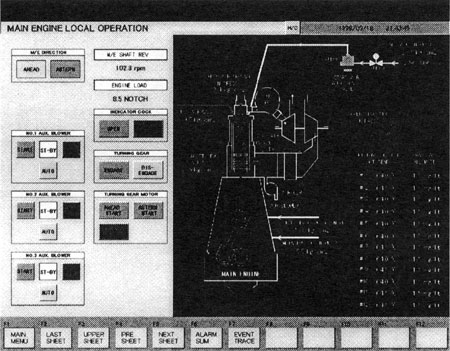
4.2 MAIN ENGINE MODEL
The main engine model works considering the remote control in the wheelhouse and simulated propulsion conditions.
The engine model is calculated under such conditions (external or internal) as weather disturbance (e.g. heavy sea, wind), condition parameters, specific gravity, calorific value and temperature of fuel oil, engine constants, position of RPM controller, ship speed with rudder angle and ship condition (laden / ballast).
From these inputs, the RPM is calculated in accordance with the cylinder pressure (mean effective pressure) and propeller tongue.
Main engine cylinder pressure is calculated and monitored by the p-兤 (dp/d兤) curve on the CRT display unit. Controllable injection timing device of the main engine is simulated. This device has a function to manually adjust the combustion condition of the main engine.
The system is equipped with a method of simulating the effect of the sea and wind. The output from the main engine model is mean effective pressure, fuel flow and actual RPM.
The main engine model includes such internal systems as fuel oil, lubricating oil, crosshead L.O., jacket cooling fresh water, starting air, combustion air and exhaust gas.
In addition, the main engine model includes turbochargers and auxiliary blowers.
Input to the model is generated according to the actual running condition, and all variables are to have dynamic responses when running conditions change.
丂
4.3 AUXILIARY MACHINERY MODEL
The auxiliary machinery model of the simulator consists of the following models.
(1) Auxiliary boiler system
The simulator has an exhaust gas economizer and an oil fired boiler with combustion control system. The boiler is the water tube type with steam separation in a steam drum and circulation pumps for forced water circulation between this steam drum and the exhaust gas economizer.
(2) Generator system
The simulator has four (4) main diesel generator engines, which are four-stroke cycle, direct injection single acting trunk piston type.