However, the adoption of EWS created high manufacturing cost maintenance cost due to some software limitations, and difficulty in hardware substitution.
But recently, from the viewpoint of the computer / electronic systems, networking systems and it environment, progresses in performance, capacity, operating software, etc. are enormous.
Without a reduction of simulation range and accuracy, we developed basic simulator software for personal computers (PC), and then manufactured and delivered the diesel engine propulsion plant training simulator.
2. SYSTEM CONFIGURATION
The diesel plant simulator uses a PC configured with an Ethernet network and server-client system using Windows NT operating system.
We developed the simulator as a training and educational tool for maritime college use. This simulator has the following features considering education for beginner level.
(1) The hardware configuration is more simplified than for ship engineers training. (2) With precise local piping system indications and other graphical indications on the CRT display unit, the trainee is able to operate machinery and valves while watching various operating status, temperatures, pressures, levels etc.
(3) The trainee is able to study the machinery plant configuration and experience various machinery plant operations with simple operations and graphical indications which are easy to understand. The addition of client computer is easy so that a large number of trainees can train by the simulator at the same time. The cost for developing and manufacturing has been lowered by using the PC network.
Since the simulator is for school educational tool we selected a large modern container ship under building that has the most basic propulsion and generator plant configuration as a model-ship.
The outline of hardware configuration and software configuration is described below.
2.1 HARDWARE CONFIGURATION
The simulator, shown in Fig. 1, consists of a Simulation Server (PC; 1 set), an Instructor Workstation (PC; 1 set), an Operator Station (PC; 2 sets), an Engine Control Console (1 set), etc. Those computers are general personal computers and connected with Ethernet network as server-client system.
Fig. 1 Outline of Hardware Configuration
2.2 SOFTWARE CONFIGURATION
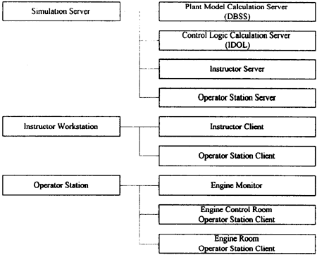
The simulator is developed with some Windows based general programming software and our original simulation software, and configured with the server-client system. Through the network of the simulator, server software communicates each other, and each server and client software communicates. The outline of software configuration is shown in Fig.2.

Fig. 2 Outline of Software Configuration
The simulation plant model was developed with our Windows base "DBSS" (Data Base Simulation System). (Refer to Fig.3) The plant simulation modeling can be realized only with a database assignment along with the fixed procedure of DBSS. With graphical man-machine interface tools, drawing only piping diagram of simulation plant model and inputting necessary performance (design) data of each element DBSS can create the necessary database for the execution of the simulation.
Fig. 3 Operation Example of DBSS (CRT display)