2.4 Outline of DDVC System
The basic concept of Direct Drive Volume Control (DDVC) System is to unify the hydraulic source system and actuator system with controlling the speed of AC-motor of hydraulic pump depending on the actuator condition.
In the conventional hydraulic system, the source system and actuator system is separated. The source system is designed to meet maximum required flow rate of actuator system and AC-motor of hydraulic pump is operated with constant speed. On the other hand, the flow rate, which is required for the actuator is controlled with servo-valve depending on the actuator condition. So, overflowed volume of system oil is returned to tank through relief valve.
Generally in those systems, the source and actuator system are connected with long pipe lines, and many kinds of pipes are extended complexly on the floor, In these pipe lines, fluid vibration occurs so often, which is depended on mismatching of source and actuator system. And those vibration causes of operation noise.
Moreover the dynamics of system is limited with the capacity of pump and it is widely lower than the one of servo-valve. The detail is shown in reference [1].

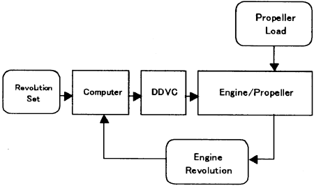
Fig. 3 Engine Revolution Control with DDVC System.
2.5 DDVC System
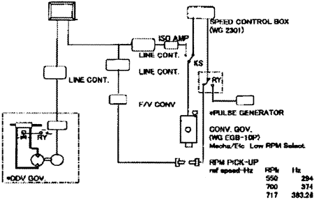
The outline of Engine Revolution Control System with DDVC system is shown in Fig.3 and the experimental system is shown in Fig. 4.
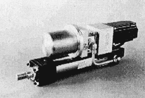
Fig. 5 shows the DDVC Hydraulic Actuator.
The DDVC system is constructed with 1] Hydraulic Cylinder, 2]Stroke Sensor, 3]Hydraulic Pump, 4]Servo-Motor, 5]Oil Tank, 6]Servo-Motor Control Unit and all of those parts except Control Unit are assembled with one body.
In this Engine Control System, DDVC actuator is attached at the end of fuel rack. On the fuel rack, conventional governor is also attached at another end and it is used usual controller, but when DDVC System were used, the governor is set at stand-by position.
The signal flow of this system is as follows,
The control signal for DDVC system is given from the control computer.
The revolution signal is feed backed to the revolution control computer, and the output on revolution control computer is given to the cylinder position controller as the set point.
The output of position controller is given to the servo-motor control unit where motor revolution control signal is outputted to motor driver depending on the positicn difference.

Fig. 4 Experimental System

Fig. 5 DDVC Actuator
3. SIMULATION AND EXPERIMENIAL SYSTEM
3.1 Conventional System
To confirm the effectiveness of DDVC system, the authors practice the computer simulation and compared with the results of on-board test.
The model ship for simulation and experiment is "Shioji Maru" (The training ship in Tokyo University of Mercantile Marine).
BACK CONTENTS NEXT