The working duration is changed with the output of the Governor, which has the function of PID Control to the error of revolution.
2.2 Conventional System
One of the conventional governor system is Mechanical hydraulic system, which has a main engine driven Hydraulic Pump and Hydraulic Calculating Units. Another is Electric Mechanical System, which has an Electric Calculating Unit and Hydraulic Actuator.
For conventional system, the constitution is shown in Fig.1.
Fig. 1 Main Engine Revolution Control System
2.3 Dynamics of Engine Revolution Control System
To study the performance of engine revolution control, the authors formulate the dynamics of this system.
Generally the dynamics of an engine revolution (Ne) is described in Eq. (1) as a function of the engine torque (Qe) and the load torque (Q1).

Where (1) denotes the inertia moment of the propeller shaft and crank shaft of main engine, and (s) denotes the Laplace operator. The engine torque (Qe) is approximated by a first order phase lag of the index of fuel injection rate (R).

In this study, we assume that engine is operated at constant revolution, and the disturbance of the load torque (Q1) is independent of the engine revolution. Thus the following linear model between the index of fuel injection rate (R) and the engine revolution (Ne) is obtained from Eq. (1) and Eq. (2),

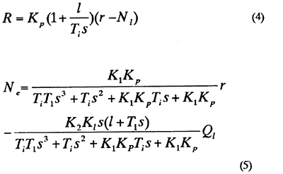
where (K 1) and (K2) are constant values. For a governor the reference value (R) of the engine revolution and the actual engine revolution (Ne) is described as follows.

Fig. 2 Engine Revolution Control System with PI Governor

, where
Kp), T1) : the proportional-gain and the integral-time of the PI governor
r : the reference revolution of the engine revolution.
Fig.2 shows the block diagram of the engine system. Each of the parameters (K1), (K2) and (T) was estimated experimentally using the training ship of Tokyo University of Mercantile Marine 'Shioji-maru', as the basis. [2], [3] Fig.2 shows the experimental and the corresponding simulation result of a step-response test of the engine speed using proportional control.
BACK CONTENTS NEXT