Alternatively the high potential of TPS..D/E can be used in combination with the Miller principle. The Miller process, with early inlet valve closing, requires a higher boost pressure compared to a conventional engine and uses this excess boost to reduce the temperature of the working medium in the cylinders through an expansion. The lower charge temperature reduces the NOx-formation during the combustion process and for gas engines it gives a larger reserve against the knock limit. The influence of the Miller process at constant engine power on the turbocharger operating point is shown by the "Line 2" in Fig.1.
The Miller process has been tested with a TPS48E on a research diesel engine in connection with a controllable two-stage injection system [2]. On this engine the NOx emission has been reduced by approximately 40% and the specific fuel consumption has been improved by about 2%. With an appropriate engine management on this engine NOx-emissions 30% below the IMO boundary curve could be reached.
In order to fulfill the engine builder's future demands as explained in this section the TPS..D/E turbocharger series provides an excellent solution.
2. DESIGN FEATURES
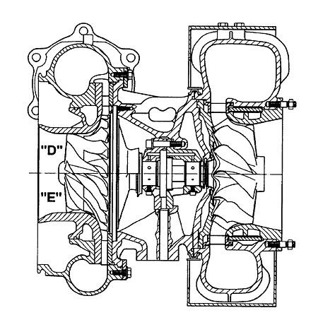
The design of the TPS..D/E turbocharger is modular and offers a high level of flexibility with a minimum of subassemblies. The modular design also allows a number of additional options, such as jet assists, inducer recirculation bypass concepts for wide compressor maps, variable turbine geometry, bypass connections, speed measurement device, compressor and turbine washing devices etc. which can be easily integrated or fitted now or in the future. This design further allows easy mounting on the engine and easy maintenance. A sectional drawing of the second largest TPS..D/E, the TPS57D/E, is shown in Fig.2.
To ensure the full range of pressure ratios required by the engines the TPS..D/E turbocharger series is available with two completely different compressor stages (see Fig.2). One stage is designed for full load pressure ratios up to 4.2 (TPS..D) and the other for full load pressure ratios up to 4.7 (TPS..E). Full load pressure ratios always correspond with 100% engine load. Due to the mechanically optimized single piece designs which include boreless compressor wheels, these pressure ratios can be reached for a wide range of applications by using an aluminum alloy as compressor material.

Fig.2: Cross-section of a TPS 57 D/E turbocharger
On the turbine side the TPS..D/E turbochargers have a mixed flow turbine with a nozzle ring suitable for pulse supercharging as well as for constant pressure applications.
When operating the turbocharger under heavy fuel conditions, radial inflow turbines have often caused material erosion due to particles reflecting from the turbine wheel.
In the TPS..D/E turbochargers coated nozzle rings are offered for heavy fuel applications reaching a lifetime up to five times longer than with standard nozzle ring material.
For pulse supercharging, gas inlet casings with two, three and four gas inlets are available in order to provide solutions for all possible pulse systems.

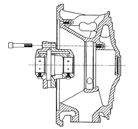
Fig.3: Disassembly of a TPS 57 D/E bearing cartridge
The gas inlet casing was designed with internal and external burst protection rings to ensure that in the worst case scenario - bursting of the turbine at its natural burst speed - all parts remain within the casing. This safety concept is used for the first time with the TPS..D/E turbochargers because traditional methods were no longer adequate for this new turbine impeller and the high power density reached.
The bearing casing of the TPS..D/E turbocharger is a single piece design, with thermally optimized bearing supports. The turbine side of the bearing casing is cooled by oil jets. This design has made it possible for the component temperatures to be kept low at critical locations in steady-state operation and also when shutting down the engine, preventing coking of the oil. The actual bearing design has two radial squeeze film backed profile bore bearings and a profiled thrust bearing located between the two radial bearings which contributes to the compact design. The oil inlet and outlet are both situated at the bottom of the bearing casing for easy mounting of the turbocharger on the engine, resulting in a compact arrangement.
Further features relate to service issues, e.g. optimized V-clamp joints designed for fully flexible casing orientation and easy disassembly, even after long periods of operation. Additional assets of this turbocharger design are the possibility to disassemble all parts from the compressor side, including the nozzle ring, and the easy access to key areas of the turbocharger, for example, for the disassembly of the bearing cartridge as shown in Fig.3.
BACK CONTENTS NEXT