丂
We have undertaken quite extensive development work in collaboration with a filter supplier (B&K) in order to ensure the cleanliness required for such systems - the very positive long-term results are described below.
Against this background, and based on the fact that the clean lube oil from the engine was at least as suitable for use in the hydraulic system as conventional hydraulic oil, we decided to base our system on fine-filtered system lube oil. This is supplied from the normal system oil pumps, providing a higher inlet pressure to the high-pressure pumps than otherwise this being yet another benefit.
丂
2.3 Fuel injection system
The general design of the system is shown in Fig.3. A common rail servo oil system using pressurised cool, clean lube oil as the working medium drives the fuel injection pump. Each cylinder unit is provided with a servo oil accumulator to ensure sufficiently fast delivery of servo oil in accordance with the requirements of the injection system and in order to avoid heavy pressure oscillations in the associated servo oil pipe system.
The movement of the plunger is controlled by a fast-acting proportional control valve (a so-called NC valve), developed by our co-operation partner Curtiss-Wright Drive Technology GmbH of Switzerland. The NC valve is, in turn, controlled by an electric linear motor that gets its control input from the cylinder control unit (see below).
This design concept has been chosen in order to maximise reliability and functionality after all, the fuel injection system is the heart of the engine, and its performance is crucial for fuel economy, emissions and general engine performance. An example of the flexibility of the fuel injection system will be given below.
The key components have a proven reliability record: the NC valves have been in series production for some ten years and are based on high-performance valves for such purposes as machine tools and sheet metal machines in car production applications where high reliability is crucial. The fuel injection pump features well-proven fuel injection equipment technology, and the fuel valves are of the conventional, well-proven and simple design.
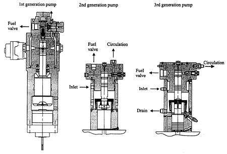
As can be seen in Fig.4, the 2nd and 3rdgenerations of pump design are substantially simpler than the 1st generation design, the components are smaller and they are very easy to manufacture. The 2nd generation pump has been in operation on the 4T50MX research engine for more than 700 hours, whereas the 3rd generation is used for the service test on the 6L60MC (see below).
The major new design feature of the 3rd generation pump is its ability to operate with heavy fuel oil. The pump plunger is equipped with a modified umbrella design to prevent heavy fuel oil from entering the lube oil system. The driving piston and the injection plunger are simple and are kept in contact by the fuel pressure acting on the plunger, and the hydraulic oil pressure acting on the driving piston. The beginning and end of the plunger stroke are both controlled solely by the fast acting hydraulic valve (NC valve), which is computer controlled.
Extensive testing has fully confirmed that the fuel injection system can perform any sensible injection pattern needed for operating the diesel engine. The system can perform as a single-injection system as well as a pre-injection system with a high degree of freedom to modulate the injection in terms of injection rate, timing, duration, pressure, single/double injection, etc. In practical terms, a number of injection patterns will be stored in the computer and selected by the control system so as to operate the engine with optimal injection characteristics from dead slow to overload, as well as during astern running and crash stop. Change-over from one to another of the stored injection characteristics may be effected from one injection cycle to the next.