Hence, the dynamic power balance produced by compressor and turbine in the gas generator is

Moreover, the dynamic power balance between power turbine and load is expressed as:

3. SIMULINK PROGRAMME AND RESETS
Thermodynamic and mechanical expressions for the gas turbine are modelled by using SIMULINK as part of MATLAB programming software. It is a software package for modelling, simulating and analysing of dynamic systems. In modelling, SIMULINK provides a graphical user interface (GUI) to build models as block diagrams. The basic mathematical models are already stored in SIMULINK Library.
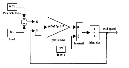
Some models, such as the iteration process for defining mean specific heat, are simple when being written in MATLAB programming. SIMULINK provides the interface called S-function for this purpose. It is incorporated in SIMULINK model by using S-Function block. Figure 2 shows the block diagram of the turbine in SIMULINK. The block diagram represents the dynamic balance of the shaft speed and power between power turbine and load.

Fig.2. Simulink Block Diagram for Power Turbine and Load
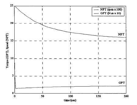
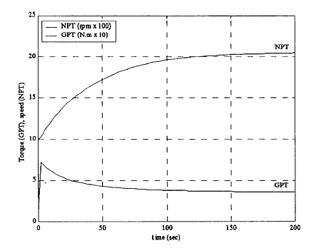
The simulation results of this modelling are presented in figure 3 and 4. The figures illustrate the change of output torque and speed of power turbine against time during the processes of an acceleration and deceleration.
It is clearly shown in figure 3 that when the gas turbine is accelerated, the power turbine speed increases until it reaches a steady-state condition. In contrast, the power turbine torque is ramped up sharply at the initial stage. Then, it gradually decreases as a result of the increase of the load when the ship is being speed up. It will reach an equilibrium point where the torque matches with the required load.

Fig.4 Power Turbine Deceleration
Figure 4 shows the power turbine's performance when decelerating. For this condition, the power turbine speed gradually decreases. The torque is sharply decreased and then, it then increases gradually to match with the required load at a given speed.

Fig.3 Power Turbine Acceleration
4. CONCLUSIONS
SIMULINK programme for modelling the gas turbine has been developed. It proved that the software provides a useful tool for analysing the dynamic performance of a gas turbine. The simulation can also performed much easier because of built-in mathematical solvers in this software.
This paper is part of a study of combined cycle gas turbine and steam turbine (COGAS) used for marine propulsion. The next step is to simulate the dynamic performance of a COGAS plant with use of SIMULINK.
5. REFERENCES
[1] Rubis, C.J. and Peterson, R.R., "Simulated Dynamics and Control of LM2500 Marine gas Turbine Engine", Proceedings of Third Ship Control Systems Symposium, Bath, England, (1972), paper IX A-2, pp.1-33.
BACK CONTENTS NEXT