Where:
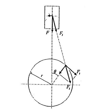
F : The resultant force of Fg + Fi
Fg : The force being given to the piston by the gas pressures in cylinder. See Eq. (3).
Fi : Inertia force of the reciprocating mass. See Eq. (4).
r : Crank radius.
A : The length of connecting rod/crank radius.
θ : Crank angle.
A : Piston area.
Pg : Combustion gas pressure.
mp : Reciprocating mass.
Fl : The force acting on the connecting rod.
Ft : Tangential force.

Fig. 1 Crank mechanism consisting of Piston and connecting rod.
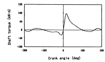
Fig. 2 shows the change of crankshaft torque on 4 cycle one cylinder engine by the Eq. (1).

Fig. 2 The change of crankshaft torque on 4 cycle one cylinder engine
2.1.2 The torsion angle of the crankshaft.
When the torque is loaded on the solid round shaft, the torsion angle can be shown by the Eq. (5).

Where:
d : Diameter of the shaft.
l : Length of the shaft.
G : Modulus of transverse elasticity of the shaft.
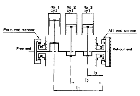
As shown in Fig.3, the relative torsion angles from the free end to the out-put end of the crank shaft during the operation can be obtained by the Eq. (5), converting the length l from the working point of torque to the out-putted of the crankshaft of each cylinder and the shaft diameter d into the value of effective length.

Fig. 3 Measuring distance of the crankshaft torsion angles.
2.2 The design of the crankshaft torsion angle detection device.
2.2.1 The detecting principle of the torsion angle
When the torque is loaded on the shaft, the shaft will be twisted and the phase difference will be caused on both ends of the shaft.
For taking out the angle signals from both ends of the shaft, both ends of the shaft must be divided by "n" equal parts for one turn of the shaft (360deg).
If you take out the each "n" numbers of signals A1〜An, B1〜Bn and measure the phase difference of a pair angle signals, you can take out the angle signals from both ends of the shaft.
BACK CONTENTS NEXT