Then the superposed point is seen as "◎" mark. The intersection of horizontal D = 0.830 m and curve p/D = 1.000 lines is plotted by "△" mark. Va = 32 kt by this "△" mark, exceeding Vac' (= 25 kt). This means that propellers of both sides have cavitation. During analysis wake fraction ω is taken as zero because of high speed.
Reforming propeller items is necessary to get new propellers of both sides.
4. NEW CENTER PROPELLER AT THE TOP SPEED
No cavitation occurrence is important. Although enlarging area of propeller is one of the methods for no cavitation, there are few propeller which exceed 1.10 in BAR. Keeping BAR 1.10 level, a trial will be done by increasing D to 1.100 m level. A-chart is overlayed by this B-chart, which is shown as Fig.3. Both A- and B-chart have been put in the right position. The intersection of SHP = 4680 ps and N = 1704 rpm lines is plotted by "○" mark on A-chart, on which the base point of the B-chart "○" mark is superposed. Then the superposed point is seen as "◎" mark.
The intersection of horizontal D = 1.100 m and curve p/D = 0.75 lines is plotted by "△" mark. By this "△" mark Vac = Vac' = 41 kt and η = 0.49. Condition of Vac = Vac' is taken to get propeller having high efficiency.
5. NEW PROPELLERS OF SIDES AT THE TOP SPEED
About one of these propellers discussion will be done under no cavitation occurrence.
A trial will be done by increasing D to 1.000 m level and decreasing BAR to 0.95 level.
A-chart is overlayed by this B-chart, which is shown by Fig.4. Both A- and B-chart have been put in the right position. The intersection of SHP = 2780 ps and N = 1706 rpm lines is plotted by "○" mark on A-chart, on which the base point of the B-chart "○" mark is superposed. Then the superposed point is seen as "◎" mark.
The intersection of horizontal D = 1.000m and curve p/D = 0.80 lines is plotted by "△" mark. By this "△" mark Vac = 41 kt, Vac' = 42 kt and η = 0.57 are obtained. Vac ≦ Vac', which has no cavitation. Condition of Vac = Vac' is taken to get propeller having high efficiency.
6. THRUST AND RESISTANCE
It is difficult to presume thrust of a propeller having cavitation. A little changing propeller items will cause propeller to get no cavitation as the previous examples. An approximate value of PT's thrust will be obtained under such a condition.
6.1 THRUST OF NEW CENTER PROPELLER AT THE TOP SPEED
Thrust horse power THP will be obtained as THP = DHP ・ η = 4680 × 0.49 = 2293 ps at the top speed Vs = 41.19 kt or vs = 21.190 m/sec. Delivered horsepower DHP equals to shaft horsepower SHP in the present calculation. Using horizontal component of THP, the thrust Tc is obtained as follows.

Angle between water line and shaft lines is 12°30' and trim angle change at the top speed 3°00'
6.2 THRUST OF NEW PROPELLERS OF SIDES AT THE TOP SPEED
About one of the propellers discussion will be done.
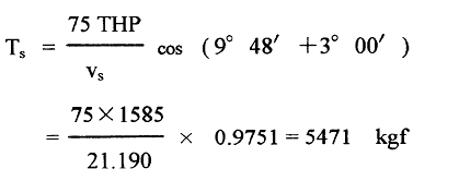
THP = DHP ・ η = 2780 × 0.57 = 1585 ps at the top speed, the thrust Ts is obtained as follows.

Angle between water line and shaft lines is 9°48' and trim angle change at the top speed 3°00’
6.3 TOTAL THRUST AT THE TOP SPEED
Total thrust T is obtained by adding these three axes' thrusts.
T = Tc + 2 × Ts
=7821 + 2 × 5471 = 18763 kgf
= 184002 N.
7. STUDY OF RESULTS
Calculation shows that about 97% of each propeller's THP contribute to horizontal component.
This T should be compared with total resistance Rs. Total thrust at Vs was obtained against not only at the top speed but also other speed as shown in Fig.5 by applying the present method to trial test data under constant D and p/D. The results are plotted by "○" marks.
One the other hand Rs were presumed by linear and quadratic regression equations based on towing tank test data using thirteen kinds of 2.5 m length models. [6]
Propulsive coefficient ηT ( = EHP/SHP ) shows 0.50 in high speed range, high is reasonable value. EHP is effective horsepower. T takes larger value than Rs up to the top speed. The difference between T and Rs increases as decreasing speed, showing enough thrust.
Seeing curves and trial test data in Fig.5, we can admit Attwood's proposition. Attwood [7] has proposed that overestimation of thrust by 10% at a design speed is recommendable in case of not having reliable information.
8. CONCLUSIONS
Reasonable presumption of PT thrust has been obtained.
The thrust of PT at the top speed was calculated by using nomogram system for blade area ratios from 0.50 to 1.10. Up to the top speed the calculations of thrust were also done to compare with resistance.
At the top speed the equilibrium of forces thrust and resistance was confirmed. Difference between thrust and resistance becomes lager as decreasing speed, showing enough thrust.