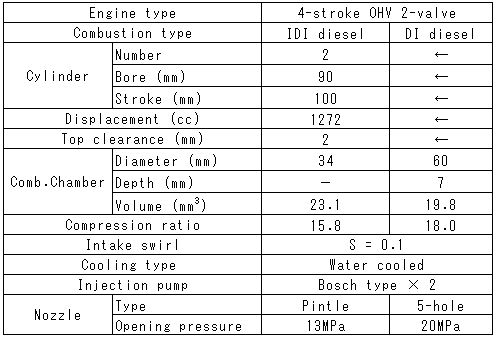
Then the heat release rate of IDI diesel engine was calculated using an assumption that the pressures in swirl chamber and main chamber were equivalent. Therefore, heat release rate of IDI diesel engine was considered to be slightly delayed from the real process [10]. NO concentration was measured by a chemiluminescence NO meter. NO emission index was expressed by an amount of NO emission per unit power. Smoke emission was measured by a Bosch smoke meter. Engine specifications are listed in Table 1. The engines used in this experiment were two-cylinder, four-stroke, overhead valve, water-cooling, natural aspirated diesel engines. Combustion chamber types of the engines were swirl chamber type for IDI diesel engine and pancake type for DI diesel engine.
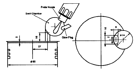
The layout of swirl chamber, nozzle position and connecting throat on IDI diesel engine are shown in Fig.2. Injection nozzle of IDI diesel engine was a pintle type and opening pressure of it was 13 MPa. The swirl chamber diameter was 34 mm and the connecting throat length was 16 min.
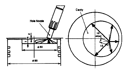
Figure 3 shows the layout of piston cavity and injection nozzle on DI diesel engine. DI diesel engine used in this study was modified from IDI diesel engine. The cylinder head of IDI diesel engine was reformed to use for DI diesel engine. The connecting throat was plugged and a hole type nozzle was newly equipped. However, the geometry of the intake port was not changed in this reforming. Then the swirl number S in this DI diesel engine was 0.1 and very low compared with conventional DI diesel engine. Owing to the modification from IDI diesel engine, matching between cavity and nozzle position was limited by head geometry. The cavity was pancake type and the diameter of it was 60 mm. Injection nozzle of DI diesel engine was five-hole nozzle and its opening pressure was 20 MPa.
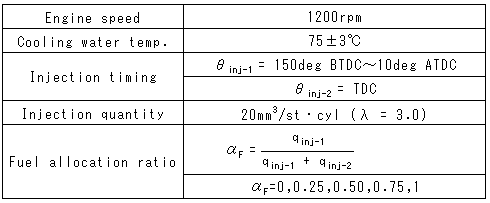
Engine operation conditions are shown in Table 2. Engine speed of test conditions was 1200 rpm. Over all excess air ratio λ of test conditions was 3.0 (amount of fuel injection was 20 mm3/stroke). Injection timing of the injection pump 1 (θinj-1) was changed from 150°BTDC to 10°ATDC and the injection timing of pump 2 (θinj-2) was fixed on TDC. Here, the supplied fuel of the first injection is denoted by qinj-1 and the second injection is denoted by qinj-2. The ratio of qinj-1 to qt (qt = qinj-1 + qinj-2; supplied fuel per cycle) is defined as the fuel allocation ratio αF:

Indicated Specific Fuel Consumption (ISFC) was calculated from an effective mean pressure which was measured by the pressure indicator. Since the experimental engines used in this study were prototypes with two injection pumps, the power output of these engines suffered undesirable power loss. It is, therefore, reasonable to discuss the difference of the thermal efficiency using IMEP and ISFC.
3. EFFECT OF EARLY STAGE INJECTION ON ROHR
Figure 4 shows the effect of early stage fuel injection on ROHR. The maximum value of ROHR in IDI diesel engine increased with the timing of fuel injection being advanced. The maximum value of ROHR in DI diesel engine increased when the injection timing was advanced up to 40。?TDC. However, it was reduced by the more advance of the injection timing over 40。?TDC.
Diffusion combustions of IDI and DI diesel engines with early stage injection were reduced. The most of fuel in IDI diesel engine was supplied in the swirl chamber. Premixing of fuel in the swirl chamber was promoted with early stage injection because of ignition delay period being long. Therefore, premixed combustion increased with early stage injection.
Amount of heat release of DI diesel engine was reduced with early stage injection. Injected spray in DI diesel engine with early stage injection was impinged to the cylinder wall. When fuel spray impinged to cylinder wall, impingement speed of it was slow, because of long distance from nozzle to cylinder wall. Therefore, fuel diffusion due to impingement was not promoted and adhering fuel increased. As a result, total heat release in the DI diesel engine with early stage injection was reduced by an increase of unburned fuel.
Table 1 Engine specification


Fig.2 Layout of swirl chamber and nozzle

Fig.3 Layout of cavity and nozzle
Table 2 Test conditions

BACK CONTENTS NEXT