The injection system was set on the top of a constant-volume vessel with observation windows [8], and fuel was injected downward into the vessel. The fuel used in this study was JIS #2 diesel fuel with a cetane number of 57.6.
丂
3. CALCULATION PROCEDURE
丂
In this study, 2-D CFD calculations for non-evaporating sprays were carried out based on the KIVA-3V code [12]. The computational mesh was a 2-D sector mesh with a radius of 30 mm and a height of 150 mm. The grid size was 0.5 mm radial 亊 2.0 mm axial, resulting the number of computational cells of 4500. The geometry of the injection nozzle, the conditions of the fuel injection rate and ambient conditions for calculations were identical with those for experiments. The fuel was injected with a droplet size equal to the nozzle radius, and subsequent atomization was calculated according to the breakup model. The break up model used was a standard TAB model [13]. The number of spray parcels to be injected was set about 900. Droplet evaporation subroutine was removed to investigate the non-evaporating sprays. Fuel used in simulations was n-dodecane (C12H26), which has the similar properties as JIS #2 diesel fuel used in the experiments.
丂
4. EFFECT OF THE RATE OF INJECTION RATE INCREASE ON FUEL DISTRIBUTION AND COMBUSTION
丂
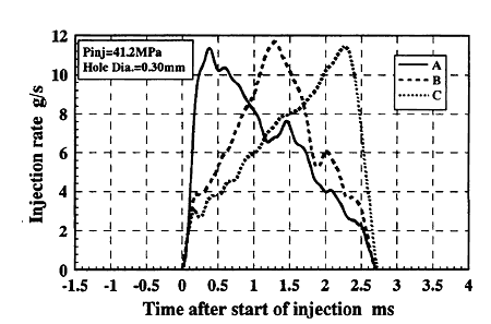
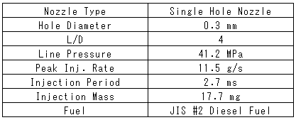
Triangular injection rate shaping with different rates of injection rate increase was examined under identical conditions of injection period, peak injection rate and total amount of fuel injected. The injection rate shaping used in the experiments is shown in Fig.2. The injection conditions including the nozzle geometry are listed in Table 1. As shown in Fig.2, three types of injection rate patterns with different slopes of injection rate rise and fall were examined. We named each injection rate pattern as A, B and C in the order of injection rate rise.
In the experiment on non-evaporating sprays, the conditions inside the vessel were set to an air pressure of 1.09 MPa and room temperature. This condition was selected to have the same ambient density with the experiment on spray combustion. In order to visualize spray evolution, the spray was illuminated by a tungsten lamp and photographed using a high speed ICCD camera. In the experiment on spray combustion, the conditions inside the vessel were set to simulate an actual diesel engine; gas pressure of 2.47 MPa and gas temperature of 870 K. The spray flame was photographed by the high speed ICCD camera and the ignition was identified by sensing the light emission of OH radical by a photo sensor.
丂
丂
High speed photographs of non-evaporating sprays, demonstrating the effects of injection rate shaping on spray evolution, are shown in Fig.3. As shown in these photographs, the rate of injection rate increase affects the temporal evolution of spray significantly. Because of the high injection rate at initial stage of injection, the spray evolution of pattern A is very fast. By contrast, the spray evolution of pattern C is very slow due to the low injection rate at initial stage, and the shape of spray is very thin until the middle stage of injection, 1.22 ms in these photographs. However, comparing the photographs of fully developed sprays, 1.35 ms of Fig.6 (a) and 2.72 ms of Fig.6 (b), the spray shapes of both injection patterns are very close.
Figure 4 shows the temporal change in spray tip penetration. The effect of the rate of the injection rate increase, as described in Fig.3, is clearly quantified in this graph. In order to compare the results of CFD calculations with those of experiments, Fig.5 shows the calculated results of spray tip penetration. Though the calculated results slightly underestimate the experimental data, good qualitative agreement can be seen between Figs. 4 and 5. This underestimation of calculated result has often been pointed out as a defect of TAB model [15].
Calculated results of 2-D fuel mass distributions are shown in Fig.6. As shown in Fig.6 (b), calculated results for injection pattern C indicate the thinner spray shapes until 1.3 ms after start of injection, corresponding well with the experimental results described in Fig.3. The characteristic of the fuel distribution deduced from these graphs is that the dense parts, indicated by the dark area, are widely distributed along the spray axis in the case of pattern A. Contrary to this tendency, in the case of pattern C, the dense parts are mainly concentrated around the spray tip. Though the spray shapes of developed spray are similar in pattern A and C, as mentioned in Fig.3, it can be pointed out that fuel injection rate shaping affects the inner structure of the spray, i.e., the spatial fuel distribution in the spray.
Figure 7 shows the one-dimensional fuel mass distribution along the spray axis for indicating the characteristic of fuel distribution quantitatively. The mass of fuel was calculated by dividing the spray into many parts along the spray axis every 5 mm and summing up the amount of fuel inside each part. In these graphs the fuel mass distribution for pattern A and C at same spray tip penetration is compared. The characteristics mentioned above can be seen clearly and quantitatively, i.e., in pattern C, the amount of fuel around spray tip is extremely high, and, in pattern A, the fuel is distributed almost uniformly along the spray axis. The reasons for these fuel distributions can be explained as follows. In the case of pattern A, the fuel injection velocity decreases with time during injection period and succeeding injected fuel droplets cannot catch up with the previously injected fuel droplets, resulting in the relatively uniform fuel distribution.