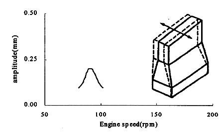
Fig.9 Results of engine main frame vibration
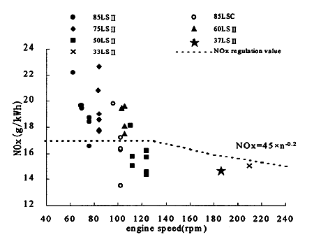
Fig.10 Result of NOx measurement for UEC-LS II/C engine
3. EXPANDED OUTPUT RANGE WITH THE NEW UEC-LSE ENGINE
3.1 Design Target
The design concepts of the UEC engine are simplicity and compactness, high reliability, easy maintenance and high economy. The UEC-LSE series was designed to enhance those UEC engine's features further more and low emissions using the latest technology based on the excellent service results of the UEC-LS II series. We have started to develop the UEC52LSE as the first UEC-LSE engine in 1998, and this is suitable for panamax bulk carrier. In 1999, we stepped up to develop the UEC68LSE, which is the best fit for cape size bulk carrier and suez max tanker. Fig.11 and Fig.12 show cross section of the UEC52LSE, UEC68LSE respectively. BMEP of the UEC-LSE is 19.0 bar and the mean piston speed is approx. 8.5m/s. BMEP and mean piston speed are increased to 5% and 6% higher than those of the existing UEC-LS II series respectively.
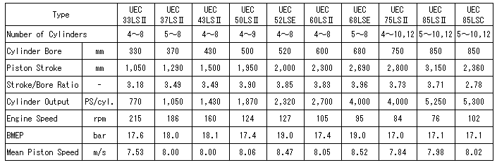
Table 2 shows the main particulars of UEC-LSE including UEC-LS II/LSC series engines.
Principal features of the construction are as below.
-Three gears for driving the camshaft (UEC-LS II has four gears except for small type, UEC33LS II, UEC37LS II)
-Hydraulic exhaust valve rotator, piston crown with forged steel, first piton ring with chrome plate, etc. are applied same as UEC-LS II series.
-The same crankshaft position as the competitor's engine for easy re-design of the engine room and shafting.
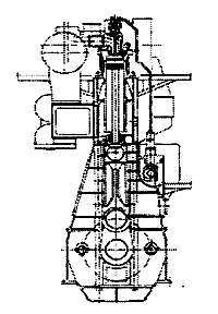
Fig.11 Cross-section of UEC52LSE
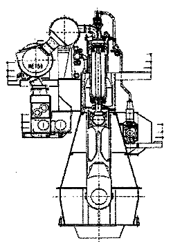
Fig.12 Cross-section of UEC68LSE
The UEC-LSE engines achieved the excellent fuel oil consumption by adopting the high efficiency MITSUBISHI-MET turbocharger, applying the CSS (controlled swirl scavenging) port of the cylinder liner, optimizing the fuel spray and the hydraulic exhaust valve rotator.
Table 2 Main particulars of UEC-LS II C/E engine
3.2 Reliability
The key points in developing of UEC-LSE engines are as follows.
-Thermal load by increasing BMEP.
-Mechanical stress by increasing maximum combustion pressure.
-Load to crankshaft and main bearing by increasing stroke bore ratio.
We applied various CAE techniques to optimize those matters as shown in Fig.13.
3.2.1 Combustion chamber
We evaluated the reliability of the combustion chamber at BMEP 19 bar as follows.
1] Temperature measurement on the existing UEC-LS II engines at BMEP 18 bar and the analysis of thermal condition on the existing engines based on the measured temperature.
2] High BMEP operation test on the production engine (UEC-LS II) and test engine in R&D center to confirm the thermal condition at high BMEP operation.
3] FEM analysis for improvement design at BMEP 19 bar by using the results of 1] and 2].
Fig.14 shows some examples of analysis results.
BACK CONTENTS NEXT