D. B. JOHNSON, D.D. BALDWIN, J.R. LONG
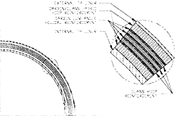
Fig. 1─CPR composite tube body wall construction.

Fig. 2─CPR Metal-to-Composite Interface, a multiple traplock configuration.
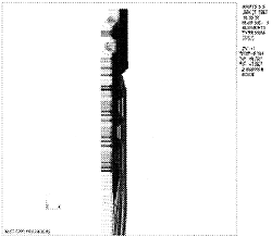
Fig. 3─CPR Finite Element Model. FEA can be a powerful design tool when combined with prototype testing.
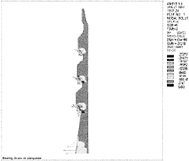
Fig. 4─FEA results such as this stress contour plot allow the designer to correlate analysis results with material and prototype testing. The relative magnitude of the nodal force vectors gives a visual indication of load share between multiple traps.
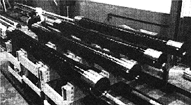
Fig. 5─Photograph of CPR specimens used for testing.
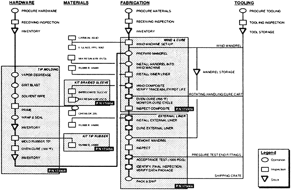
Fig. 6─Manufacturing flow diagram for the CPR test specimens.
前ページ 目次へ 次ページ