2-5. Theoretical Study for Restraining Hunting
To theoretically explore and substantiate the effectiveness of the use of the gas-extraction valve in restraining the hunting as outlined in the foregoing, the authors devised a numerical plant dynamics simulator representing the diesel generating plant fitted with the SCR system for use in conducting the theoretical study by numerical simulation.
Outline of Numerical Plant Dynamics Simulator Entire Plant Modeling
The unstable plant dynamic characteristics resulting from the placement of the SCR system large in heat capacity between the dynamo engine and its turbocharger are attributable basically to a delay in energy transmission, which can, therefore, be evaluated by modeling the energy flow that takes place in this plant configuration.
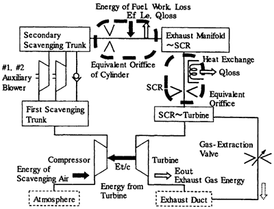
Fig. 4 shows an outline of the computation model, which consists of equipment volumes and their interconnecting throttles, valves, turbocharger, etc, and by which the weight of air passing through the equipment volumes and the changes in temperature and pressure within respective equipment volumes due to heat transfer were calculated in computation time increments. The principal component elements were modeled as follows.

Fig. 4 Outline of The Computation Model
Principal Component Element Modeling
1] SCR System Computation Model
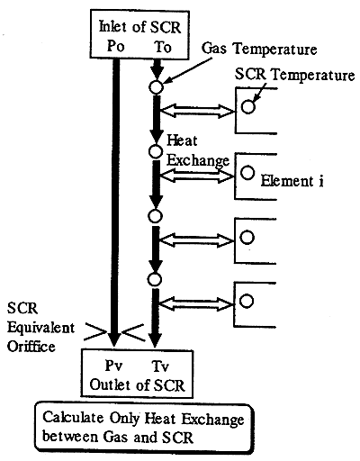
Fig. 5 shows a SCR system computation model. What is at issue here is not the flow of exhaust gases through the SCR system but the exchange of heat between the exhaust gases and SCR system. Also, to reduce the computation load, the SCR system was treated as element exclusively for exchanging heat with exhaust gases; the flow of exhaust gases was simulated by installing an equivalent throttle corresponding to the SCR system gas passage flow resistance.

Fig. 5 SCR system Computation Model
Also, the delay in exhaust-gas energy transmission due to the large heat capacity of SCR system was found difficult to accurately simulate when the SCR system was treated as a single element performing the heat exchange. The SCR system computation model, therefore, was so formulated as to consist of more than one element so that the temperature distribution in the SCR system longitudinal direction could be taken into account.
The exchange of heat between the SCR system and exhaust gases was calculated by the following equations. Also, as the change in temperature of the SCR system elements was dominantly from the exchange of heat with exhaust gases. the heat transfer between the separate SCR system elements was neglected.
The energy equation, applicable to the SCR system is as follows.

Also, the energy equation applicable to exhaust gases is as follows.

The temperature of “j” of “i”th element + 1 point of time is given as follows.
From (1), the SCR system temperature equation is written as:

BACK CONTENTS NEXT