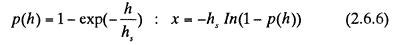
where p(h) is CDF of the ridge sail height and h, is the mean ridge sail height.
The thickness of the consolidated layer in a ridge is distributed using the following equation:

where, hcons is the thickness of the consolidated layer, hi is the mean ice thickness and x is the random number 0〜1.
For the calculation of ridge resistance, the method (Malmberg, 1983)is again used. The ridge resistance is comprised of resistance at the ship's bow, resistance of paralle1 midbody.
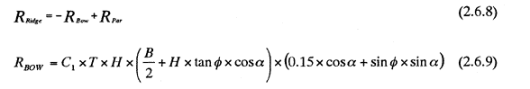
where C1 is constant value determined according to the soil mechanics. T is the draft, H is the keel depth, B is the breadth, α is the waterline entrance angle at stem, and φ is the stem angle. Rpar is somewhat lengthy and referred to the original paper (Lindquist, 1989).
In the ridged ice, the resistance of compressivc ice is considered more carefully. A compressive ice field increases the ice resistance of the ship due to the convergence of the ice. In the program the direction of the compression is assumed to be 90 degree to the ship centerline. The additional resistance in the compressive ice; △R is given in the equation (2.6.10) and equation (2.6.11).
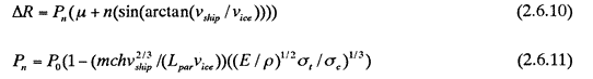
where vship is ship speed, vice is the speed of the converging ice field, Lpar is the length of the parallel midbody, Hi is the level ice thickness, E is the elastic modulus, ρ is the density of ice, σt is the bending strength,σc is the compressive strength, μ is the friction coefficient, m=1.5, n=2.5, c=0.65 and P0=1
Based on the assumption that the sum of the resistance of level ice, consolidated layer, ridged ice and compressive ice is equal to TNET, in the equation (2.6.1). Making use of the probabilistic technique and the repetitive calculation, the distribution of the ship speed is obtained.