Ѓ@
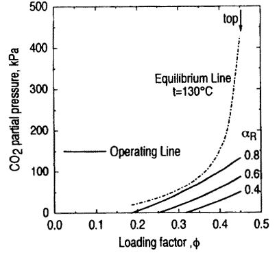
In the absorbing column, the operating lines get close to the equilibrium line at the terminal points of column but CO2 transfer driving force does not result in a pinch state.
In the stripping column, the operating lines get close to the equilibrium line at a pinch point around the middle of columnЃF they get closer to the equilibrium line, as the CO2 recovery ratio increases, and eventually contact with the equilibrium line, which denotes that there is no driving force of CO2 mass transfer. Therefore, in the range of the calculation conditions of this analysis, the attainable maximum CO2 recovery ratios are determined by the equilibrium condition at the pinch point in the stripper.
When the operating lines for the stripper are assumed to be linear, they are explained by the pairs of the loading factor and the CO2 partial pressure both at the top of the column, (ѓУ h PT), and at the bottom of the column, (ѓУ 1 P1). The lowest loading factor, ѓУ1 and the highest one,ѓУh are related by Eq.1, which is derived from CO2 mass balance in the absorber, that is, CO2 mole difference between ѓУ h andѓУ 1 stands for CO2, moles absorbed in the absorber.
Ѓ@
ѓУ 1 =ѓУ h - GAyEXѓїR/(LACMEA/ѓПL(1)
Ѓ@
where yEX stands for CO2 mole fraction of exhaust gas, CMEA for MEA concentration of solution, and ѓПL for density of solution.
The CO2 partial pressure at the bottom, p1 can be regarded as 0 kPa.
The CO2 partial pressure at the top, pT, is approximately calculated by Eq. 2, which is derived according to the followingЃF
1)Ѓ@conservation exists between the CO2, stripped and the steam condensed in the stripper, where it is taken into account that steam of 2 moles per 1 mole of stripped CO2 condenses since the heat of the reaction between CO2 and MEA per 1 mole of CO2 is roughly equal to the latent heat of water of 2 molesЃF
2)Ѓ@the total pressure in the stripper, Ptot, is almost the same of the pressure of the saturated steam multiplied by the mole fraction of water in the solution at the stripping temperatureЃF
3)Ѓ@C02 flow rate at the top equals that recovered from the exhaust gasЃF
4)Ѓ@mass flow of solution is the same between the absorber and the stripper.
Ѓ@
PT=ptot{(1/yEX ѓїR (Gs/LA)/(Gs/LA)-1}-1Ѓ@(2)
Ѓ@
By both Eq. 1 and Eq. 2, it is understood that the operating line gets nearer to the equilibrium line as the CO2 recovery ratio, ѓїR, increases, since ѓУ1 becomes smaller and PT gets largerЃF and as the ratio of the gas-to-liquid feed rate ratio of the stripper to that of the absorber, (Gs/Ls)/(GALA), becomes smaller, the operating line gets nearer to the equilibrium line and the attainable maximum CO2 recovery ratio becomes smaller.
Ѓ@
5.2Ѓ@Effect of Gas and Liquid Feed Rates on Output Power
Heat of the steam required by the reboiler, QRB, is equal to that of the steam used in the stripper which is the sum of the steam at the top of the stripper and the condensed steam used for stripping. The ratio of CO2 and steam at the top of the stripper can be derived by using Eq. 2. Being taken into account that steam of 2 moles per 1 mole of the stripped CO2 condenses, the heat balance of the steam gives Eq.3 for heat required by the reboiler, QRB.
Ѓ@