|
4. UPORABA POMORSKIH SIMULATORJEV ZA DODATNO IZOBRAŽEVANJE REŠEVALNIH SKUPIN
The simulation of rescue drill was carried out on four different simulators, as follows:
・Day one: on the ships handling and GMDSS simulator
・Day two: on the GMDSS simulator
・Day three: on the Engine Room and Cargo Handling - VLCC simulator
・Day four: simulation exercise on the VLCC simulator
・Day five: simulation exercise on the CC simulator and a short recapitulation
4.1 Simulation of a grounded tanker with the use of the ships handling simulator.
Participants were given only a demonstration of a few basic scenarios of grounding, like the rudder and engine failure, blackout, grounding due to collision avoidance and nautical failure in fog. The participants did not have the best overview of this part of the project, as the simulator was at that point equipped only with the visualization on computer monitors and the model did not display the impact of shallow water and the interaction between vessels. Besides, the visualization itself was automatically terminated and did not allow any further simulation. All these limitations soon lead to the improvement of ships handling simulators. Today we have a navigating bridge on the moving platform, which together with two virtual bridges, makes up a good basis for the execution of such projects. All three bridges have also a communication center and are connected to the GMDSS lab, in which each computer may represent its individual part, thus contributing to the overall rescue operation. The latter may be conducted by means of sending telexes being supervised from the instruction station. A similar access to the organization of rescue operation was carried out at the Kobe University of Mercantile Marine [8].
4.2 Simulation of the preparation of pumps by the engine room simulator.
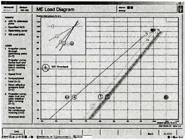
At the first stage the Engine Room Simulator was also used only for a demonstration simulation. The participants were only observing the demonstration prepared in advance. With the steering system failure scenario we simulated a gradual decrease of water depth, finally resulting in grounding. As the model at that time did not have an automatic system for a graphical display of engine loading, these data was drawn graphically. A modern engine model enables display of main engine loading while refloating; likewise it is possible to show all transfer procedures of responsibility from the bridge to the engine room and to the local control. Besides, there is an option to shut off the engine safety systems.
Fig.3 ME load diagram on engine room simulator
At the second stage all participants by themselves prepared the cargo discharge pump for operation on the VLCC tanker. The simulation was aimed at showing the time and the preparation procedures needed for the steam system to be ready for lightering. The ship is namely not ready for lightering immediately after grounding. The simulation of pump preparation is carried out by the engine-room simulator, as this enables a much more detailed display than the cargohandling simulator.
Fig.4 Steam turbine pump
4.3 Simulation of lightering with the cargo handling simulator.
Before the simulation of lightering we first determined the grounding force by using simple procedures shown in the relevant literature [17]. Below is shown a brief practical calculation:
Displacement: D1 := 201500
Draughts before grounding:
F1 := 18.17・m
A1 := 18.28・m
M1 := 18.31・m
Draughts after grounding:
F2 := 17.02・m
A2 := 19.14・m
M2 := 18.03・m
Grounding lever: LCGR := 208.85・m
Central tank 1 lever: LCGCT1 := 235.23・m
Grounding mom. = saving mom. LCGR・R = LCGCT1・X
|